PicoScope 7 Automotive
Available for Windows, Mac, and Linux, the next evolution of our diagnostic scope software is now available.
Automotive guided tests
Library of examples on how to perform tests when using PicoScope.

Training
Our collection of training videos, articles, guides and information on training courses.

Waveform library
The Waveform Library is a global database of waveforms uploaded by PicoScope users.

Case studies
Real-life case studies show how the professionals use PicoScope to diagnose vehicle faults.

A to Z of PicoScope
Detailed description of various PicoScope software and hardware features.

Videos
Training resources and demonstrations on PicoScope and the Automotive Diagnostics Kit.

Newsletter
Archive of our monthly Automotive Newsletters.

Documentation
Download manuals, brochures, posters, and training materials.

Reviews and awards
Accolades for the preferred diagnostic tool for service centers and vehicle manufacturers.

In the words of a recent post on our Forum "Maths Channels are so cool", and here, Pico Technology's Steve Smith explains why:
Many users of the PicoScope 4000 Series Automotive scope will have already discovered the frequency coupling feature built into the scope, which can measure a digital MAF meter output. Whilst this is an invaluable feature it is only available on one channel and so measuring frequency on multiple channels becomes an issue......or does it?
Over and above the frequency coupling feature we have a multitude of math calculations we can make to an input signal (waveform) using the "Math Channels" feature of PicoScope.
Clicking on 'Tools>Maths Channels' from your PicoScope screen will reveal numerous "Built-in" maths channels that will assist you when looking at the input signals for any channel you wish. These "Built-in" maths channels will simply invert, add, subtract, divide, or multiply any combination of waveforms to any channels of interest (the "Built-in" maths channels use Channels A and B).
Let's take a look at a CAN communication signal using Channels A CAN HI and B CAN LO. With the waveform on screen click on 'Tools>Maths Channels' and tick the box adjacent to A-B, then click OK. This will then display a 3rd (maths) channel with the calculation you have requested.
In this case: CHA A - CHA B = CAN HI - CAN LO = 0 V and 2 V which is this message hidden within CAN HI and CAN LO transmission.
Below we can now see the 3rd (Math) channel but it is difficult to interpret because of the interference in the CAN HI circuit. If you now right-click on your scope screen, select "Channels" and untick boxes "A" and "B", you will remove these channels leaving just the math channel behind.

The remaining math channel clearly reveals the impact on the CAN communication message stored within the CAN signals due to the interference seen on Channel A.

With math channels you are not tied down to the selection in the "Built- in" menu as you can create your own maths channel, and here is where maths channels really do become cool!
Let's take a typical PWM signal of 0 V to 5 V as seen with the digital MAF sensor and assume you want to calculate the frequency of the PWM. Remember with the majority of digital MAF meters, an increase in air flow is directly proportional to an increase in the output frequency of the 5 V signal.
To calculate frequency you need to "create" a math channel and here is the theory:
To calculate frequency the signal must past through zero volts (crossing point), yet our signal travels from 0 V to 5 V. A clever tip therefore is to split the signal in half (2.5 V) and use this value as follows in the formula you are about to create. We use "-2.5" to effectively move the zero crossing point into the middle of the signal output. This allows the maths channel to calculate the number of crossing points in a given time to display the frequency, i.e. the number of times the signal crosses 2.5 volts.

Select 'Tools>Maths Channels' and then 'Create'. Click on 'Advanced' and then the "freq" button. When "freq( )" appears in the formula box, put your cursor in between the two brackets "( )" and type A-2.5, the whole formula will look like freq(A-2.5). Click 'Next', choose any colours, names, and ranges. It is best at this stage to set a manual override to the actual frequency range you require (in the example below I have selected 0 Hz to 300 Hz) and finally click 'Finish'. A new 3rd (math) channel will appear and will plot the frequency of the channel you have requested (in our case 'A-2.5' is a frequency math channel for Channel A).
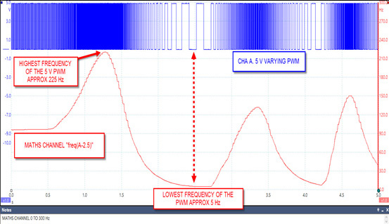
Above we can now see how the PWM changes over time by plotting the frequency with our math channel. This feature now becomes invaluable allowing you to test dual digital MAF meters on "V" configuration engines, control valves (diesel pump), actuators (EGR) and solenoids (turbo boost control) etc. Basically anything controlled via PWM can be tested using PicoScope not only for the integrity of the signal but speed of the signal over time.
Remember when creating your math channel if you have a 0 V to 12 V PWM signal your formula will be freq(A-6) assuming you wish to measure frequency on Channel A. When setting your scale for the maths channel 0 Hz to 2000 Hz will cover most control solenoids such as diesel pump inlet and turbo boost control.
Go ahead and play with the maths channel feature as it will open up a whole new world of measuring techniques revealing even more about your input signal. For any support you need regarding PicoScope please contact support@picotech.com.

Steve Smith highlights the risk of 'budget fuses' and uses PicoScope to show just how dangerous they can be.
This customer couldn't understand how his vehicle had sustained fire damage to both the roof harness and roof lining, when a fuse was in place to protect the circuit.
After some discussion the customer revealed he had purchased an array of budget fuses online, and had fitted one of these 'budget' 10 A mini blade fuses to the circuit in question. We decided to investigate the fuses out of interest, and here are our findings.
The first scope trace demonstrates an OEM 10 A fuse blowing at 60 A peak after
35 ms...

The second scope trace shows the inferior 'budget' 10 A fuse not failing, and allowing near 70 amps through for over a second! At this point I had to let go of the link wire because it was getting hot, hot, hot!

The 0 V moments in the second trace are due to connection issues during the test process...with sparks flying and fingers getting very hot you can imagine why this might occur. Also, you'll notice at the end of the trace there are some voltage drops, this is where the test cables we had created had started to melt...don't forget this fuse should have blown at 10 A, and now our test cables are melting due to the fuse simply not doing its job.
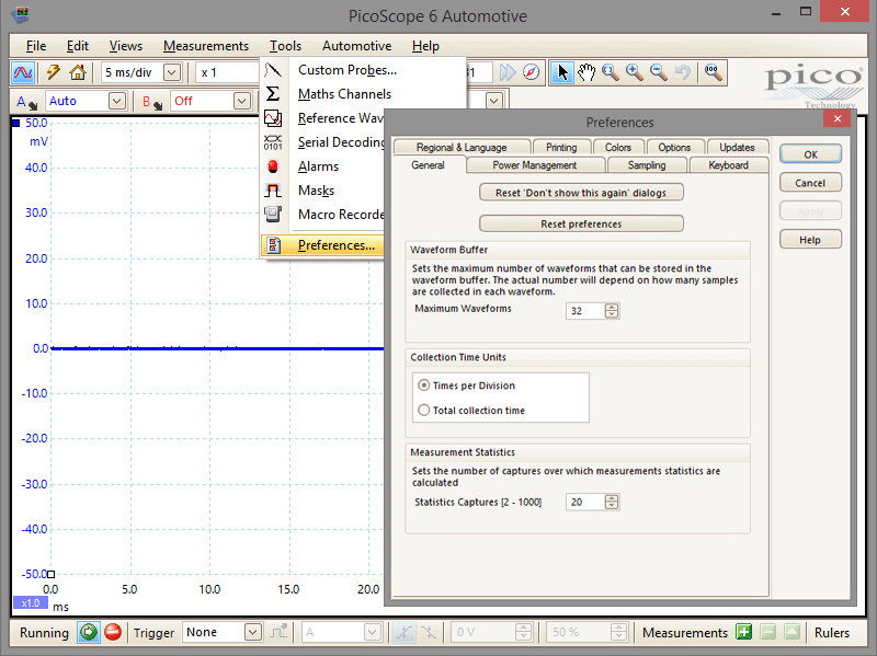
Did you know PicoScope 6 Automotive can store up to 10,000 waveforms?
Whilst the default number of waveforms is 32, this can easily be changed. To do this, choose "Tools > Preferences" to reveal the Preferences dialogue. In the Waveform Buffer section you can either use the spinner to select the number of waveforms you would like, or simply type the number into the box. The actual number of waveforms that are collected will depend on the selected sample rate, as the higher the sample rate the more buffer memory that is used.
 |
Black rubber case Using our S-hook you can easily hang your PicoScope from the bonnet/hood catch when working in the engine bay - giving you easy access to the scope and leads without the worry of damaging them. The PicoScope protective rubber case is suitable for PicoScope 4000 Series Diagnostic Scopes and PicoScope 3000 Series automotive oscilloscopes. While the navy blue rubber case is included for free with the Advanced Vehicle Diagnostics Kit, you can buy either the black or navy blue individually from the Miscellaneous Accessories section of our website. |
 |
30 A large jaw current clamp The TA189 provides improved sensitivity, lower noise and faster response. Featuring a 25 mm jaw size this clamp is suitable for measuring battery drain over long periods. It also features an auto power-down facility to save battery life when not in use (this feature can be disabled for battery drain / shutdown current testing). Using advanced Hall Effect sensors for improved sensitivity and high external field rejection as well as closed loop control for increased accuracy, the TA189 delivers a breakthrough in range and accuracy to meet the challenges of modern vehicles. To view more information or to buy the 30 A Large jaw current clamp, please visit our website. |
|
Autonet Mobility show 2014: In 2014, the Autonet Mobility Show continues its expansion! This is an event that a distributor of Pico Technology hosts. The already traditional Cluj Napoca event will remain a reference standard for the industry and will take place between the 9th and 10th May. You will find Pico Technology at the show at stand C17. 9th - 10th May 2014 Autonet Mobility show 2014 |
 |
|
Automechanika Dubai: With 1,482 exhibitors spanning 58 countries and 24,141 visitors from 130 countries, Automechanika Dubai is geared up to supply intermediate markets. Renowned as the region's largest and most comprehensive trade and networking exhibition for the automotive aftermarket, Automechanika Dubai offers you a unique spectrum of products from the fields of automotive parts, systems, car washing, tyres & batteries, workshop and filling-station equipment, IT products and services, accessories and tuning. You will find Pico Technology in the UK pavilion. 3rd - 5th June 2014 Automechanika Dubai |
 |
Please visit Pico Exhibitions for the latest list of exhibitions and trade shows that Pico and its representatives will be attending.
Thanks to our continuing success and growth Pico are always seeking talented people to join our company.
Please visit http://pico.jobs/ to see our current vacancies. We look forward to hearing from you!
Our latest software releases are available as free downloads. To check which release you are using, start the software and select Help > About.
To make sure that your Pico newsletter reaches your inbox every month, add newsletters@picotech.com to your email address book or safe list. If you found this newsletter useful, please recommend it to your friends and colleagues. Back issues are available from our newsletter archive.
By subscribing to our newsletter, you agree to receive one email a month plus no more than two special announcements a year. Our use of your email address is governed by our privacy policy.
UK HQ:
Pico Technology, James House, Colmworth Business Park, St. Neots, Cambridgeshire,
PE19 8YP, England
Tel.: 01480 396395 (+44 1480 396395)
Fax: 01480 396296 (+44 1480 396296)
Pico Technology North America Inc.
320 N Glenwood Blvd.
Tyler
TX 75702
United States
Tel:+1 800 591 2796 (Toll Free)
Email: sales@picotech.com
Web: www.picotech.com
Web technical support: www.picotech.com/tech-support/
Twitter: picotech
Facebook: Pico-Technology


