PicoScope 7 Automotive
Available for Windows, Mac, and Linux, the next evolution of our diagnostic scope software is now available.
Automotive guided tests
Library of examples on how to perform tests when using PicoScope.

Training
Our collection of training videos, articles, guides and information on training courses.

Waveform library
The Waveform Library is a global database of waveforms uploaded by PicoScope users.

Case studies
Real-life case studies show how the professionals use PicoScope to diagnose vehicle faults.

A to Z of PicoScope
Detailed description of various PicoScope software and hardware features.

Videos
Training resources and demonstrations on PicoScope and the Automotive Diagnostics Kit.

Newsletter
Archive of our monthly Automotive Newsletters.

Documentation
Download manuals, brochures, posters, and training materials.

Reviews and awards
Accolades for the preferred diagnostic tool for service centers and vehicle manufacturers.

I wanted to pick up on a new decoder for PicoScope 7. It has been out for a while, but you might not think that it would have a role in automotive.
Quadrature encoding is used by rotary position sensors to transmit information about the angle and direction of a rotating shaft. On a motor, for example, in the form of a pair of binary signals. This type of sensor has been used on electric motors for some time and we can decode these signals to determine what the ECU is seeing when the motor is turning.
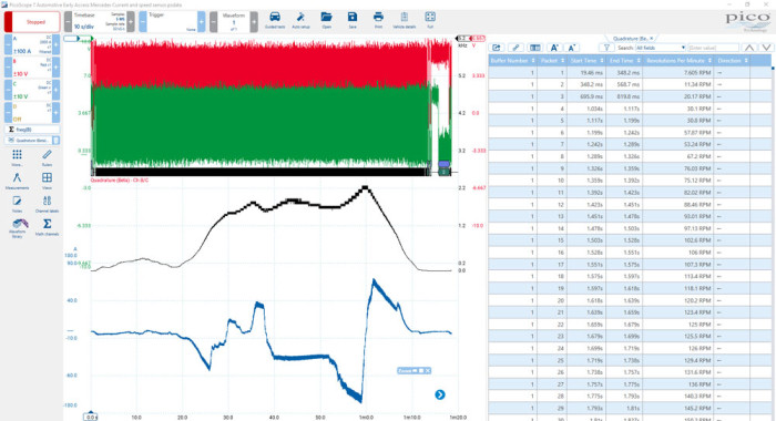
Below is an image taken from a Tesla motor fitted to a Mercedes B Class. There are two square wave outputs for the sensor. I've also included the battery current to get an idea of when the motor is turning.
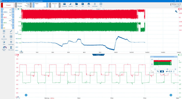
The encoder determines the speed and direction the shaft, based on the interaction between the two signals.
There are some known criteria that is required when setting up the quadrature decoder: which signal is the leading signal, and what is the number of pulses per rotation. As I quickly found out, though, this information is not readily available. This should not, however, stop us from using the decoder.
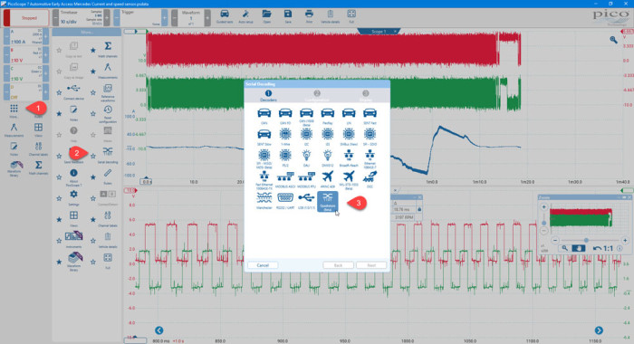
To add the decoder to your capture, click More > Serial Decoding and select Quadrature.
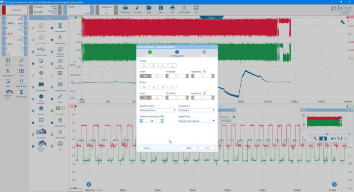
In the Configuration settings, you need to tell the decoder on which channel it can find the applicable data.

1. In this example, the relevant data is on Channels B and C.
2. The signal is sitting between 0 V and 5 V. Selecting a threshold of 3 V will put us close to the middle of the signal, allowing a clean crossing point. Hysteresis is not overly important here as the crossing point is very clean, so leave the software to apply this automatically. The second signal should be added with, hopefully, similar settings!
3. The Display settings have several options: speed, displacement and transition clock. For this particular application, we will use Speed.
4. Pulses per revolution is defaulted to 24. If you can find this information, please use it, but otherwise you can just leave it as it is. This does mean that the speed value you obtain from the decoder will not represent that of the shaft being monitored by the encoder.
5. A leads B is - this refers to your two signals and specifying which one is the leading signal. You have the options of Clockwise and Anticlockwise. Again, this may not be known, but once the decoder is added to the graph, you will have a direction arrow in the table. It is up to you, but it will become obvious which is the forward direction depending on how you are driving the motor in either forward or reverse.
6. Speed Units - have several options as well, but the one that we are most familiar with is RPM.
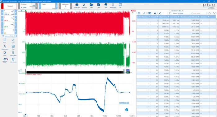
The decoder will appear on the bottom of the screen, same as with all PicoScope decoders, but I have moved it to the side to make it easier to see.
As you can now see, we have a speed and a direction given in the table. If you double-click/tap on a line in the table, it will take you to the relevant section in the graph.

From the table, you can see that the first two packets have different directions. When we took this capture, we reversed briefly before putting the vehicle into drive and travelling forward. You could amend the decoder by changing the A leads B to the alternative option.
Finally, as the speed is reflected by the frequency change in the signal, we can add a frequency math channel for one or both signals to display the change in speed of the shaft.
I hope this helps in some way, and if you have any feedback for the Quadrature decoder, please let us know.


