PicoScope 7 Automotive
Available for Windows, Mac, and Linux, the next evolution of our diagnostic scope software is now available.
Automotive guided tests
Library of examples on how to perform tests when using PicoScope.

Training
Our collection of training videos, articles, guides and information on training courses.

Waveform library
The Waveform Library is a global database of waveforms uploaded by PicoScope users.

Case studies
Real-life case studies show how the professionals use PicoScope to diagnose vehicle faults.

A to Z of PicoScope
Detailed description of various PicoScope software and hardware features.

Videos
Training resources and demonstrations on PicoScope and the Automotive Diagnostics Kit.

Newsletter
Archive of our monthly Automotive Newsletters.

Documentation
Download manuals, brochures, posters, and training materials.

Reviews and awards
Accolades for the preferred diagnostic tool for service centers and vehicle manufacturers.

| Symptom: | |
| Author: | Rfmotors1 |
There are many reasons why the aircon may fail but only one way to rectify any of them, it is logical approach based on evidence obtained by tools and observation.
In this case we have a simple complaint: “No cold air from aircon vents”.
The condition can be replicated so this is not intermittent problem, diagnostic tester shows no DTC and temperature sensor on evaporator shows value close to ambient temperature via the live data reading by diagnostic tester. There is also refrigerant pressure 7 bar at stationary and 23 bar when AC on Low temp and engine idle. The pressure goes very high which means the AC compressor does its job, simple visual check revealed the radiator fan is not running and we know there is not stored any DTC in AC or Engine ECU.
We have narrowed the diagnostic to “Radiator fan does not work”
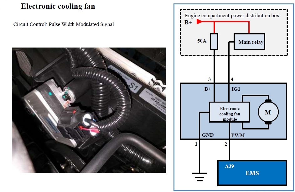
Now it starts to be interesting, we have the simplified diagram which shows 4 wires connector (The pin 3&4 are thick wires as main power supply, pin 2&4 are thin wires).
Scope connection:
First step was to see what is happening on the 4 wires of radiator fan socket, simple back pin all 4 wires and connect 4 leads to scope plus one common ground to battery negative. Very important is to keep the fan socket plugged in and try not to move with wires avoiding the “accidental fix”.
Set the scope to 20V on all channels and let’s say 1sec time base and click run, then start the engine and set the AC ON, temperature to Low and let’s have a look on the scope screen.
That’s it:
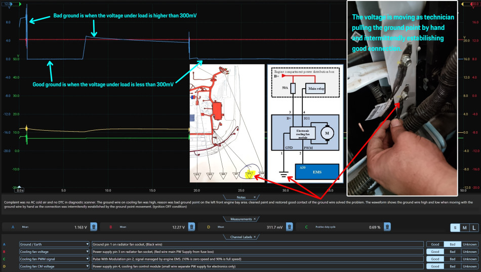
This simple test has proven the fan unit and the engine ECU are OK, the only problem is the ground “high” under the load. (See the blue waveform channel “A”)
On the scope screen:
The channel A is the ground pin number 1 on the fan socket. (See the next pictures)
The ground wire pin 1 was constantly high, voltage was around 8V and when the technician played the ground point by hand, the voltage was dropping low or rising depending on the intermittent connection caused by the cable movement.
Let me draw one scenario that I see in most workshops:
The technician unplugs the radiator fan connector and measures the power supply on the pins 3 and 4 where he reads the battery voltage and marks it OK as this is clearly good based on this wiring diagram.
Then he measures the continuity of all 4 wires and the result is also OK, continuity is good.
What is the conclusion?
Replace the radiator fan unit and then test if it works right? But the new fan is still not working, we have a big problem now. Such situation would lead to re-testing all the wires again and probably decide to replace Engine ECU, because there is nothing else.
So, after new Engine ECU is installed, the radiator fan is still not working!!!
Dead end, parts installed and many labour hours spent without any result, not talking about the vehicle down time.
How could be this avoided?
The answer is in technician basic knowledge plus using correct tools and applying the diagnostic strategy, the event driven diagnostic process. In this case it is diagnostic training and oscilloscope. The time to diagnose this car was 5 min plus one hour where was searching the wire diagram, unpack and connect the scope and removing air filter box as it was not done in work bay with available tools.
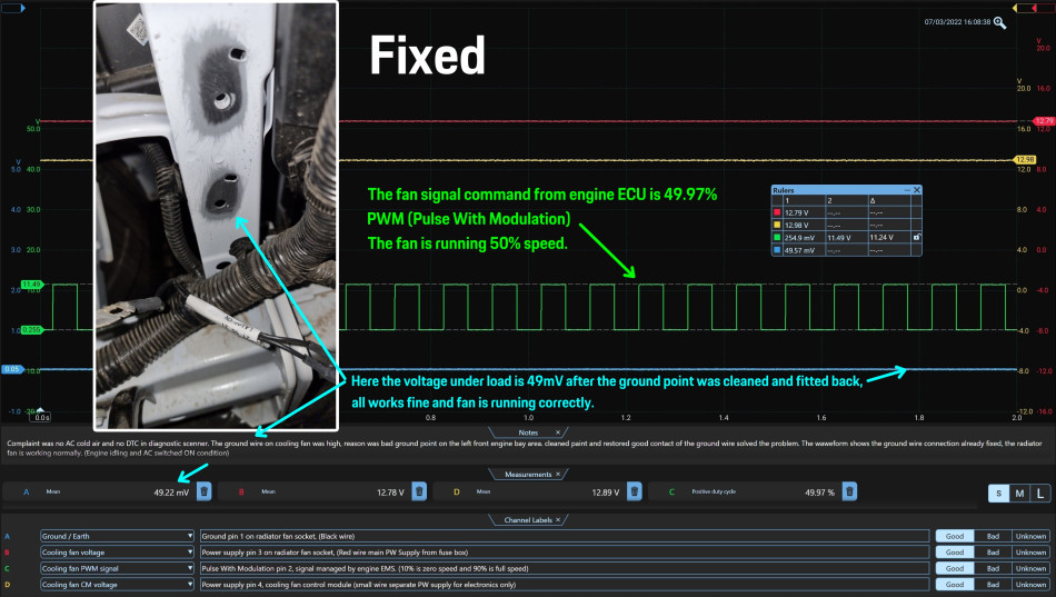
The Fix:
The Ground point G14 had to be cleaned from paint, the technician also cleaned all the ground points in this area to avoid possible repeat repair in case more ground points would have bad connection.
(the picture below explains the details, ground point is fixed)
Most of the labour time got to remove the air filter box to reach the ground point G14 and clean the ground points by removing the paint with sandpaper.
Summary:
This was simple case study, the focus was on describing the correct diagnostic strategy and possible misleading if its not followed. The importance of understanding the voltage drop and its relation with electric current.
The diagnostic tester can only display DTC and values which the ECU can read and analyse. The technician must use oscilloscope to see and understand the real data and values in combination with theoretical knowledge and proper practical training. In this case it was Picoscope very basic kit that has done the job but basically any scope will do good on such simple circuit.
I hope it was interesting case and thank you for reading.
Roman


