PicoScope 7 Automotive
Available for Windows, Mac, and Linux, the next evolution of our diagnostic scope software is now available.
Automotive guided tests
Library of examples on how to perform tests when using PicoScope.

Training
Our collection of training videos, articles, guides and information on training courses.

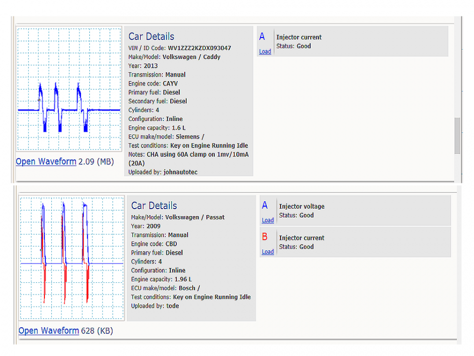
Waveform library
The Waveform Library is a global database of waveforms uploaded by PicoScope users.

Case studies
Real-life case studies show how the professionals use PicoScope to diagnose vehicle faults.

A to Z of PicoScope
Detailed description of various PicoScope software and hardware features.

Videos
Training resources and demonstrations on PicoScope and the Automotive Diagnostics Kit.

Newsletter
Archive of our monthly Automotive Newsletters.

Documentation
Download manuals, brochures, posters, and training materials.

Reviews and awards
Accolades for the preferred diagnostic tool for service centers and vehicle manufacturers.


20 A / 60 A DC (low amps) current clamp
*At Pico we are always looking to improve our products. The tool used in this guided test may have been superseded and the product above is our latest version used to diagnose the fault documented in this case study.
The purpose of this test is to examine a VAG-PD injector current under engine idle, acceleration and overrun conditions.
WARNING
This test involves measuring a potentially hazardous voltage.
Please ensure you follow manufacturers' safety instructions and working practices and ensure the rated voltage for all accessories you are using meets or exceeds the expected voltage.

View connection guidance notes.
Note
The orientation of the current clamp relative to the wire will determine whether it has a positive or negative output. If a live waveform does not appear on your screen, or appears to be inverted, try reversing the orientation of the clamp.


These example waveforms show the injector current under different operating conditions.
Example 1: The first injector phase is pre-injection and the second is the main injector phase.
Example 2: As the engine speed is raised, the control module increases the duration of the main injector phase.
Example 3: On overrun, only the pre-injection phase remains.
Go to the drop-down menu bar at the lower left corner of the Waveform Library window and select, injector current.
You can refine your search by selecting, make VW,


The piezo-mechanical unit injectors are located in the cylinder head and the wiring runs through a circular multi-plug at the rear of the head to the individual injectors. The injectors are unlike common-rail injectors in that the high fuel pressure is generated by an additional rocker-arm running from the camshaft and acting directly onto the injectors. There is no high-pressure pump the injectors can operate across a wide range of pressures from 130 to 2,200 bar.
This system is referred to by the Volkswagen Audi group as Pumpe-Düse (PD).
There may be up to five injection phases:
Piezo injectors have a major advantage over conventional electromagnetic injectors, a very quick reaction time up to four times faster.
Piezo injectors contain a stack of about 300 thin ceramic plates. When the switching voltage is applied the plates expand and open the nozzle needle allowing fuel into the cylinder.
Figure 3 shows a piezo element in its two different states. Illustration 1 shows the stack with no supply voltage and illustration 2 shows the increase in height of the stack when the supply voltage is switched on.
Note; Once the stack is in the injector open position, it does not need to have a continuous supply current and remains in the open state until the close command. The open and close commands are the positive and negative current spikes in the waveform. For this reason, never disconnect the injector multi-plug with the engine running. If the injector is in the open state it could hydraulic-lock the engine with diesel fuel.
The engine will cut out if the control module detects any faults with the injectors or driver circuit.
Selection of component-related Diagnostic Trouble Codes (DTCs):
P0251 - Injection Pump Fuel Metering Control "A" Malfunction (Cam/Rotor/Injector)
P0252 - Injection Pump Fuel Metering Control "A" Range/Performance (Cam/Rotor/Injector)
P0253 - Injection Pump Fuel Metering Control "A" Low (Cam/Rotor/Injector)
P0254 - Injection Pump Fuel Metering Control "A" High (Cam/Rotor/Injector)
P0255 - Injection Pump Fuel Metering Control "A" Intermittent (Cam/Rotor/Injector)
P0256 - Injection Pump Fuel Metering Control "B" Malfunction (Cam/Rotor/Injector)
P0257 - Injection Pump Fuel Metering Control "B" Range/Performance (Cam/Rotor/Injector)
P0258 - Injection Pump Fuel Metering Control "B" Low (Cam/Rotor/Injector)
P0259 - Injection Pump Fuel Metering Control "B" High (Cam/Rotor/Injector)
P0260 - Injection Pump Fuel Metering Control "B" Intermittent (Cam/Rotor/Injector)
GT146
Disclaimer
This help topic is subject to changes without notification. The information within is carefully checked and considered to be correct. This information is an example of our investigations and findings and is not a definitive procedure.
Pico Technology accepts no responsibility for inaccuracies. Each vehicle may be different and require unique test
settings.
We know that our PicoScope users are clever and creative and we’d love to receive your ideas for improvement on this test. Click the Add comment button to leave your feedback.
MikeW
December 10 2018
Hello Jacob George, firstly apologies for such a delayed reply. We have a guided test for both current and voltage on a VAG pd injector. Go to guided tests, actuators, diesel injectors, VAG PD current voltage and earth. Hope this will answer your question.
Jacob George
March 01 2018
Hi, could you please explain how to test the supply voltage used at the time of expanding the piezo crystal and contract the crystal ?


