PicoScope 7 Automotive
Available for Windows, Mac, and Linux, the next evolution of our diagnostic scope software is now available.
Automotive guided tests
Library of examples on how to perform tests when using PicoScope.

Training
Our collection of training videos, articles, guides and information on training courses.

Waveform library
The Waveform Library is a global database of waveforms uploaded by PicoScope users.

Case studies
Real-life case studies show how the professionals use PicoScope to diagnose vehicle faults.

A to Z of PicoScope
Detailed description of various PicoScope software and hardware features.

Videos
Training resources and demonstrations on PicoScope and the Automotive Diagnostics Kit.

Newsletter
Archive of our monthly Automotive Newsletters.

Documentation
Download manuals, brochures, posters, and training materials.

Reviews and awards
Accolades for the preferred diagnostic tool for service centers and vehicle manufacturers.


20 A / 60 A DC (low amps) current clamp
*At Pico we are always looking to improve our products. The tool used in this guided test may have been superseded and the product above is our latest version used to diagnose the fault documented in this case study.
The purpose of this test is to investigate the current value and saturation time within a Distributorless Ignition System (DIS) primary coil.
WARNING
This test involves measuring a potentially hazardous voltage.
Please ensure you follow manufacturers' safety instructions and working practices and ensure the rated voltage for all accessories you are using meets or exceeds the expected voltage.

View connection guidance notes.
Note
The orientation of the current clamp relative to the wire will determine whether it has a positive or negative output. If a live waveform does not appear on your screen, or appears to be inverted, try reversing the orientation of the clamp.
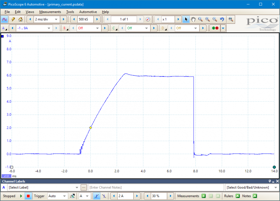
In the example waveform above, the current limiting circuit can be seen in operation. The current switches on as the dwell period starts and rises until the requisite 5-10 amps (depending on system) is achieved within the primary circuit, at which point the current is maintained until it is released at the point of ignition.
The dwell will expand as the engine revs are increased. This is to maintain a constant coil saturation time, hence the term 'constant energy'. If one time ruler is placed at the beginning of the dwell period and the other on the induced voltage line, the coil saturation time can be measured. This will remain exactly the same regardless of engine speed.
Go to the drop-down menu bar at the lower left corner of the Waveform Library window and select, DIS / wasted spark ignition primary current


The waveform will show a curving line that indicates the speed at which the coil is being 'saturated'. The flatter the line, the longer it is taking to 'fill' the coil with voltage. The waveform flattens out for a time, where the current is being maintained by the amplifier once it has reached its requisite current. The current is held until the amplifier releases the earth path, when the waveform drops vertically. This vertical line is also important, as a 'sloping' line indicates that the amplifier is not switching fast enough and the induced voltage will suffer as a result.
GT168
Disclaimer
This help topic is subject to changes without notification. The information within is carefully checked and considered to be correct. This information is an example of our investigations and findings and is not a definitive procedure.
Pico Technology accepts no responsibility for inaccuracies. Each vehicle may be different and require unique test
settings.
We know that our PicoScope users are clever and creative and we’d love to receive your ideas for improvement on this test. Click the Add comment button to leave your feedback.


