PicoScope 7 Automotive
Available for Windows, Mac, and Linux, the next evolution of our diagnostic scope software is now available.
Automotive guided tests
Library of examples on how to perform tests when using PicoScope.

Training
Our collection of training videos, articles, guides and information on training courses.

Waveform library
The Waveform Library is a global database of waveforms uploaded by PicoScope users.

Case studies
Real-life case studies show how the professionals use PicoScope to diagnose vehicle faults.

A to Z of PicoScope
Detailed description of various PicoScope software and hardware features.

Videos
Training resources and demonstrations on PicoScope and the Automotive Diagnostics Kit.

Newsletter
Archive of our monthly Automotive Newsletters.

Documentation
Download manuals, brochures, posters, and training materials.

Reviews and awards
Accolades for the preferred diagnostic tool for service centers and vehicle manufacturers.


Back-pinning Probe Set

Flexible Back-pinning Probe

Premium Test Lead: BNC to 4 mm, 3 m

Premium Test Leads: Set of four leads 3 m (TA125 - TA128)
*At Pico we are always looking to improve our products. The tools used in this guided test may have been superseded and the products above are our latest versions used to diagnose the fault documented in this case study.
The purpose of this test is to observe the Diagnostic Trouble Code (DTC) flash codes that are generated at the Mazda 25-pin Data Link Connector (DLC).
Please note that this sequence is based on the 25-pin DLC fitted to Mazda variants as listed in the Fault Code Table.
Once the scope has been correctly connected to the 25-pin DLC socket:
WARNING: Disconnecting the battery may erase the memory from ancillary devices such as clocks and radios.
Important Note: This sequence is for the Mazda variants listed in the Fault Code Table. For other manufacturers, check if the vehicle is equipped with a 25-pin DLC connector and also check to see if the above test can be carried out. Serious damage to the PCM will occur if the test is carried out on a vehicle that does not support the above test method. Refer to the manufacturer's wiring and technical information for further support.
The sequence begins with a long pulse, indicating the start of the code-reading sequence from the PCM. The example waveforms show codes in the 4-digit EOBD/OBDII format, but other variants of Mazda give a two-digit code flash sequence. Consult the manufacturer's technical information for two-digit codes.
The 4-digit code in Code Sequence 1 is indicated by 4 groups of signals.
Putting these four digits together gives Code 0100, which is the EOBD Code for "Mass Air Flow (MAF) sensor/volume air flow (VAF) sensor circuit malfunction".
There are no pulses after the start pulse, indicating that all digits are 0. The table below tells us that:
Code P0000 = EOBD Code for No Fault Found.
Therefore there are no fault codes present on the vehicle.
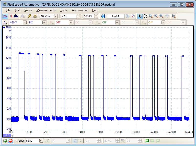
There is one code that is repeated as it is the only code stored in the PCM. The table below tells us that:
Code P0110 = EOBD Code for Intake Air Temperature (IAT) Sensor.
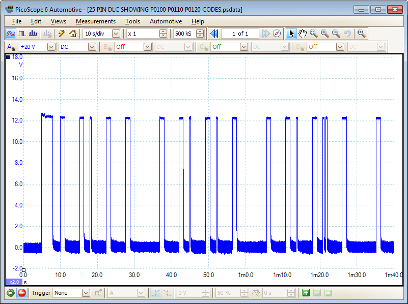
The PCM is signalling 3 codes. The table below tells us that:
Code P0100 = EOBD Code for Mass Air Flow (MAF) sensor/volume air flow (VAF) sensor circuit malfunction.
Code P0110 = EOBD Code for Intake Air Temperature (IAT) Sensor.
Code P0120 = EOBD Code for Thottle Position (TP) sensor A/Accelerator pedal position (APP) sensor A circuit malfunction.
The engine management system is constantly monitored by the PCM as the engine is running under different loads and conditions. All of the input and the output signals are monitored at all times. This is done so that the PCM can keep control of the engine and maintain optimum running conditions at all times. The PCM checks the values from the sensors and compares them with the information stored in the ROM (Read Only Memory) of the PCM. Based on the information stored, the PCM changes the commands to the actuators to alter any parameters to keep optimum running.
While the PCM is reading from ROM and reading all the signals from the sensors and actuators, thus monitoring the operating parameters of the engine, it is also monitoring the tolerances and ranges of each sensor and actuator to see if they are working correctly. When the PCM sees that a component or tolerance is breached then it will initiate a DTC (Diagnostic Trouble Code) which is stored in the RAM section of the PCM, often known as KAM (Keep Alive Memory), or in the EEPROM (Electronically Eraseable Programmable Read Only Memory). The DTC is then stored until action is taken: the fault is rectified on a self-check system, or an instruction is sent to the PCM to clear the DTC and the system is rechecked to ensure that it is operating correctly again.
There are a number of different methods for accessing fault codes depending on the system used on the vehicle - EOBD, OBD I or OBD II:
This legislation requires that vehicles manufactured from 1988 onwards be equipped with a system that is controlled electronically by a computer and is capable of monitoring itself during operation. Any malfunction in the system that leads to an effect in the exhaust emissions has to illuminate a warning light on the dashboard and present a stored DTC. The DTC must accessible and readable with the use of on-board facilities such as Flash Code, LED, Test Lamp, Oscilloscope.
The legislation that supports OBD-II applies to vehicles that are manufactured from 1994 onwards (Spark Ignition Engines) and 1996 onwards (Compression Ignition Engines). The main features fitted and that have to be monitored constantly are as follows:
The key features for DTCs are as follows:
| CODE PART | POSSIBLE ARRANGEMENT | MEANING |
|---|---|---|
| 1 | B | BODY Control Code |
| 1 | C | CHASSIS Control Code |
| 1 | P | POWERTRAIN Control Code OBD II |
| 1 | U | UNDEFINED - Used for Network Systems, CAN Bus |
| 2 | 0 | Fault Code given under the SAE testing guidelines |
| 2 | 1 | Fault Code given under the Manufacturer's guidelines |
| 2 | 2 | Fault Code given under the Manufacturer's guidelines |
| 2 | 3 | Reverse Fault Code |
| 3 | 1 | Fuel and Air Measurement System |
| 3 | 2 | Fuel and Air Measurement System |
| 3 | 3 | Ignition System |
| 3 | 4 | Exhaust Control System |
| 3 | 5 | Engine Speed and Idling Control System |
| 3 | 6 | PCM, Computer Control & Output Signals |
| 3 | 7 | Transmission Control Systems |
| 4 | 01 to 99 | Assignment of System Components |
Figure 5 - Structure of Standard Fault Codes
The Fault Code Table below is specific to the vehicles listed.
| FAULT CODE TABLE - MAZDA VARIANTS | |||
| Model: | 323 (BG) - 323 ESTATE 1.6/4X4 (BW) - 323 (BA) - 323 1.3/1.5/1.8 (BJ) - 323 2.0 D/TD (BJ) - 626/MX-6 (GE) - 626/ESTATE 1.8/2.0 (GF/GW) - 626/ESTATE 2.0 TD (GF/GW) - XEDOS 6/9 - MX-3/MX-5 | ||
| Year: | 1989 - 2003 | ||
| Engine Code: | BP, BP-DOHC, B3, B3E, B6-SOHC, B6-DOHC, B6E, FP, FS, KF, KJ, KL, K8, RF, RF-CX, FR-TURBO, ZL, Z5 | ||
| System: | MAZDA EGI - MAZDA EDC | ||
| EOBD CODE | LOCATION OF FAULT | POSSIBLE CAUSE OF FAULT | |
| P0 | Refer to EOBD Diagnostic Trouble Codes. | - | |
| P2 | Refer to EOBD Diagnostic Trouble Codes. | - | |
| U0 | Refer to EOBD Diagnostic Trouble Codes. | - | |
| P1100 | Mass Air Flow (MAF) Sensor - Circuit Intermittent | Wiring, MAF Sensor | |
| P1101 | Mass Air Flow (MAF) Sensor - Circuit Intermittent | Wiring, MAF Sensor | |
| P1110 | Intake Air Temperature (IAT) Sensor 2 | Wiring, IAT Sensor | |
| P1112 | Intake Air Temperature (IAT) Sensor 2 - Circuit Intermittent | Wiring, IAT Sensor | |
| P1113 | Intake Air Temperature (IAT) Sensor 2 | Wiring, IAT Sensor | |
| P1117 | Engine Coolant Temperature (ECT) Sensor - Circuit Malfunction | Wiring, ECT Sensor | |
| P1120 | Throttle Position (TP) Sensor - Low Input | Wiring short to Earth, TP Sensor | |
| P1125 | Throttle Position (TP) Sensor - Circuit Intermittent | Wiring, TP Sensor | |
| P1130 | Fuel trim (FT) - Control limit exceeded | Intake/Exhaust leak, fuel pressure/pump, EVAP/EGR system, wiring, HO2S | |
| P1131 | Heated Oxygen Sensor (HO2S) - Low Voltage | Intake/Exhaust leak, fuel pressure low, hose connection, HO2S/wiring short to earth, Injector(s), MAF Sensor/Wiring | |
| P1132 | Heated Oxygen Sensor (HO2S) - High Voltage | Intake/Exhaust leak, fuel pressure low, hose connection, HO2S/wiring short to positive, Injector(s), MAF Sensor/Wiring | |
| P1170 | Oxygen Sensor (O2S)/Heated Oxygen Sensor (HO2S), bank 1 - incorrect signal. | Intake leak, fuel pressure/pump, wiring, O2S/HO2S, Injector(s), ECT Sensor, MAF Sensor, Spark Plugs | |
| P1173 | Oxygen Sensor (O2S)/Heated Oxygen Sensor (HO2S), bank 2 - incorrect signal. | Intake leak, fuel pressure/pump, wiring, O2S/HO2S, Injector(s), ECT Sensor, MAF Sensor, Spark Plugs | |
| P1182 | Fuel Shut-Off Solenoid | Wiring, Fuel Shut-Off Solenoid | |
| P1189 | Fuel Injection pump position/speed sensor | Wiring, Fuel injection pump speed sensor | |
| P1190 | Module Coding Plug | Wiring, Module Coding Plug | |
| P1195 | Barometric Pressure (BARO) Sensor | Wiring, BARO Sensor, PCM | |
| P1196 | Ignition Switch, Start Signal - Circuit Malfunction | Wiring, Starter Motor | |
| P1221 | Traction Control (TCS) System - Malfunction | Wiring, TCS Malfunction | |
| P1226 | Fuel Quantity Adjuster Position Sensor - Circuit Malfunction | Wiring, Fuel quantity adjuster position sensor | |
| P1250 | Fuel Pressure Regulator Control Solenoid | Wiring, Fuel pressure regulator control solenoid | |
| P1252 | Fuel Pressure Regulator Control Solenoid 2 | Wiring, Fuel pressure regulator control solenoid | |
| P1279 | Fuel Quantity Adjuster Position Sensor - Range/ Performance Problem | Wiring, Fuel quantity adjuster position sensor | |
| P1298 | Fuel Quantity Adjuster Control Module - Circuit Malfunction | Wiring, Fuel quantity adjuster control module | |
| P1312 | Fuel Injection Timing Valve | Wiring, Fuel injection timing valve | |
| P1318 | Fuel Injection Timing Valve Position Sensor - Circuit Malfunction | Wiring, Fuel injection timing valve position sensor | |
| P1319 | Fuel Injection Timing Valve Position Sensor - Range/Performance Problem | Wiring, Fuel injection timing valve position sensor | |
| P1345 | Camshaft Position (CMP) Sensor - No Signal | Wiring, Sensor Supply Voltage, CMP Sensor | |
| P1402 | Exhaust Gas Recirculation (EGR) Valve Position Sensor | Wiring, EGR Valve position sensor | |
| P1409 | Exhaust Gas Recirculation (EGR) Valve - Circuit Malfunction | Wiring, EGR Valve | |
| P1474 | Engine Coolant Blower Motor Relay - Circuit Malfunction | Wiring, Engine Coolant Blower Motor Relay | |
| P1485 | Exhaust Gas Recirculation (EGR) Solenoid - Vacuum | Wiring, EGR Solenoid | |
| P1486 | Exhaust Gas Recirculation (EGR) Solenoid - Vent | Wiring, EGR Solenoid | |
| P1487 | Manifold Absolute Pressure (MAP) Sensor Solenoid | Wiring, MAP Sensor Solenoid | |
| P1496 | Exhaust Gas Recirculation (EGR) Valve, Motor Coil 1 | Wiring, EGR Valve | |
| P1497 | Exhaust Gas Recirculation (EGR) Valve, Motor Coil 2 | Wiring, EGR Valve | |
| P1498 | Exhaust Gas Recirculation (EGR) Valve, Motor Coil 3 | Wiring, EGR Valve | |
| P1499 | Exhaust Gas Recirculation (EGR) Valve, Motor Coil 4 | Wiring, EGR Valve | |
| P1500 | Vehicle Speed Sensor (VSS) - Intermittent Signal | Wiring, VSS | |
| P1504 | Idle Air Control (IAC) Valve | Wiring, IAC Valve | |
| P1508 | Bypass Solenoid 1 | Wiring, Bypass Solenoid | |
| P1509 | Bypass Solenoid 2 | Wiring, Bypass Solenoid | |
| P1521 | Intake Manifold Air Control Solenoid 1 | Wiring, Intake Manifold Air Control Solenoid | |
| P1522 | Intake Manifold Air Control Solenoid 2 | Wiring, Intake Manifold Air Control Solenoid | |
| P1523 | Intake Manifold Air Control Solenoid 1 | Wiring, Intake Manifold Air Control Solenoid | |
| P1524 | Intercooler Bypass Solenoid | Wiring, Intercooler Bypass Solenoid | |
| P1525 | Air Bypass Valve Solenoid - Vacuum | Wiring, Air Bypass Valve Solenoid | |
| P1526 | Air Bypass Valve Solenoid - Vent | Wiring, Air Bypass Valve Solenoid | |
| P1540 | Air Bypass Valve Control | Hose leak/blockage, Wiring, Air Bypass Valve Actuator/Solenoid | |
| P1562 | Engine Control Module (PCM) - Supply Voltage Low | Battery, Alternator, Wiring | |
| P1601 | Data BUS, TCM | Wiring, PCM, TCM | |
| P1602 | Engine Control Module (PCM)/Immobilizer Control Module - Communication Error | Wiring, Reader Coil, Ignition Key, Immobilizer Control Module, ECM | |
| P1603 | Ignition Key - Not Programmed to PCM | PCM Incorrectly/Not Programmed | |
| P1604 | Engine Control Module (PCM) / Immobilizer Code Not Stored | PCM Incorrectly/Not Programmed | |
| P1606 | Engine Control Relay | Wiring, Engine Control Relay | |
| P1608 | Engine Control Module (PCM) | PCM | |
| P1609 | Engine Control Module (PCM) Knock Control | PCM | |
| P1621 | Engine Control Module (PCM) / Immobilizer Control Module - Immobilizer Codes do not Match | Incorrectly Programmed Immobilizer Control Module/PCM | |
| P1622 | Engine Control Module (PCM) / Immobilizer Control Module - Ignition Key Codes do not Match | Incorrect/Damaged Key, PCM Incorrectly Programmed | |
| P1623 | Engine Control Module (PCM) - EEPROM Error | PCM | |
| P1624 | Engine Control Module (PCM) - Immobilizer Deactivation Signal Missing | Battery Disconnected - Erase Trouble Code, Immobilizer System Malfunction | |
| P1627 | PCM/ABS Electrical Connection - Communication Error | Wiring, ABS Control Module, PCM | |
| P1631 | Alternator - Output Voltage Low | Wiring, Alternator Drive Belt, Alternator | |
| P1632 | Engine Control Module (PCM) - Supply Voltage Low | Wiring, Alternator, Battery | |
| P1633 | Engine Control Module (PCM) - Supply Voltage High | Wiring, Voltage Surge when Battery Disconnected, Alternator | |
| P1634 | Alternator - Output Voltage High/Battery Voltage Low | Wiring, Alternator, Battery | |
| P1649 | Engine Control Module (PCM) - Defective | PCM | |
| P1650 | Power Steering Pressure (PSP) Switch | Wiring, PSP Switch | |
| P1720 | Vehicle Speed Sensor (VSS) | Wiring, Speedometer, VSS | |
| P1743 | Torque Converter Clutch (TCC) Solenoid | Wiring, TCC Control Solenoid | |
| P1744 | Torque Converter Clutch (TCC) Solenoid | Wiring, TCC Solenoid | |
| P1765 | Shift Timing Solenoid, 3-2 | Wiring, Shift Timing Solenoid | |
| P1770 | Overrunning Clutch Solenoid | Wiring, Overrunning Clutch Solenoid | |
| P1790 | Throttle Position (TP) Sensor | Wiring, TP Sensor | |
Important Note: This sequence is for the Mazda variants listed in the Fault Code Table above. For other manufacturers, check if the vehicle is equipped with a 25-Pin DLC connector and also check to see if the above test can be carried out. Serious damage to the PCM will occur if the test is carried out on a vehicle that does not support the above test method. Refer to manufacturer's wiring and technical information for further information.
Fault code information reproduced by kind permission of Autodata.
GT173-EN
Disclaimer
This help topic is subject to changes without notification. The information within is carefully checked and considered to be correct. This information is an example of our investigations and findings and is not a definitive procedure.
Pico Technology accepts no responsibility for inaccuracies. Each vehicle may be different and require unique test
settings.
We know that our PicoScope users are clever and creative and we’d love to receive your ideas for improvement on this test. Click the Add comment button to leave your feedback.