PicoScope 7 Automotive
Available for Windows, Mac, and Linux, the next evolution of our diagnostic scope software is now available.
Automotive guided tests
Library of examples on how to perform tests when using PicoScope.

Training
Our collection of training videos, articles, guides and information on training courses.

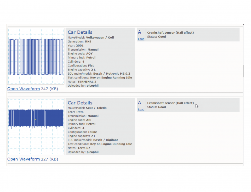
Waveform library
The Waveform Library is a global database of waveforms uploaded by PicoScope users.

Case studies
Real-life case studies show how the professionals use PicoScope to diagnose vehicle faults.

A to Z of PicoScope
Detailed description of various PicoScope software and hardware features.

Videos
Training resources and demonstrations on PicoScope and the Automotive Diagnostics Kit.

Newsletter
Archive of our monthly Automotive Newsletters.

Documentation
Download manuals, brochures, posters, and training materials.

Reviews and awards
Accolades for the preferred diagnostic tool for service centers and vehicle manufacturers.


Multimeter Probes

Back-pinning Probe Set

Flexible Back-pinning Probe

PicoScope Battery Clip
*At Pico we are always looking to improve our products. The tools used in this guided test may have been superseded and the products above are our latest versions used to diagnose the fault documented in this case study.
The purpose of this test is to examine the voltage output signal from a Hall Effect crank position (CKP) sensor with the engine running.
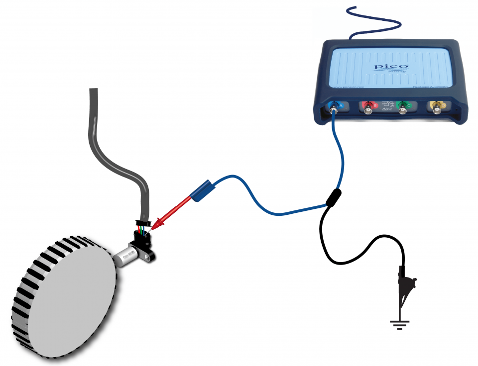
View connection guidance notes.
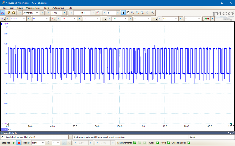
This known good waveform has the following characteristics:
Go to the drop-down menu bar at the lower left corner of the Waveform Library window and select Crankshaft sensor (Hall effect)

The Crankshaft Position (CKP) sensor provides an Engine Control Module (ECM) with its primary timing reference signal. The ECM uses it to calculate the engine speed and position for accurate injection control etc. The signal is also used to detect engine speed anomalies from misfires etc.
Unsurprisingly, Hall effect CKP sensors use the Hall effect, which produces a potential difference (known as the Hall voltage) across the width of a conductor, when it has a current flowing through its length and a magnetic field is applied perpendicular to the current (i.e. through the bottom-top direction of the conductor). When the current is fixed, the greater the magnetic field strength, the greater the Hall effect voltage.
The sensors have in-built conditioning circuits that convert the Hall effect voltage to a stable digital signal output switching between 0 V and 5 V. As they consume power, Hall effect CKP sensors require voltage feed and earth circuits.
The sensor is accompanied by a pulse wheel, typically consisting of 36 or 60 teeth and arranged about the flywheel circumference. As the pulse wheel rotates, each tooth passes through and disturbs the sensor’s magnetic field, which modulate the Hall voltage. In response, the digital sensor output switches either from low to high (0 V to 5 V) or high to low (5 V to 0 V), depending on the sensor circuitry. Therefore, the sensor output is a square wave with its switching frequency dependent on the crankshaft speed.
The pulse wheels have one or more two teeth gaps which indicate specific crankshaft positions to the ECM. These are often mistaken as TDC or BDC indicators.

The CKP sensor signal is critical to ECM operation and failures can cause symptoms such as:
Related failures are:
Selection of component related Diagnostic Trouble Codes (DTCs)
P0016
P0315
P0335
P0336
P0337
P0338
P0339
P0385
P0386
P0387
P0388
P0389
P1324
P1335
P1336
P1345
P1372
View more
GT012
Disclaimer
This help topic is subject to changes without notification. The information within is carefully checked and considered to be correct. This information is an example of our investigations and findings and is not a definitive procedure.
Pico Technology accepts no responsibility for inaccuracies. Each vehicle may be different and require unique test
settings.
We know that our PicoScope users are clever and creative and we’d love to receive your ideas for improvement on this test. Click the Add comment button to leave your feedback.


