PicoScope 7 Automotive
Available for Windows, Mac, and Linux, the next evolution of our diagnostic scope software is now available.
Automotive guided tests
Library of examples on how to perform tests when using PicoScope.

Training
Our collection of training videos, articles, guides and information on training courses.

Waveform library
The Waveform Library is a global database of waveforms uploaded by PicoScope users.

Case studies
Real-life case studies show how the professionals use PicoScope to diagnose vehicle faults.

A to Z of PicoScope
Detailed description of various PicoScope software and hardware features.

Videos
Training resources and demonstrations on PicoScope and the Automotive Diagnostics Kit.

Newsletter
Archive of our monthly Automotive Newsletters.

Documentation
Download manuals, brochures, posters, and training materials.

Reviews and awards
Accolades for the preferred diagnostic tool for service centers and vehicle manufacturers.


Back-pinning Probe Set

Flexible Back-pinning Probe

PicoScope Battery Clip
*At Pico we are always looking to improve our products. The tools used in this guided test may have been superseded and the products above are our latest versions used to diagnose the fault documented in this case study.
The purpose of this test is to evaluate the correct operation an AC excited camshaft sensor based on the AC voltage supply and AC voltage return signal during engine run conditions.
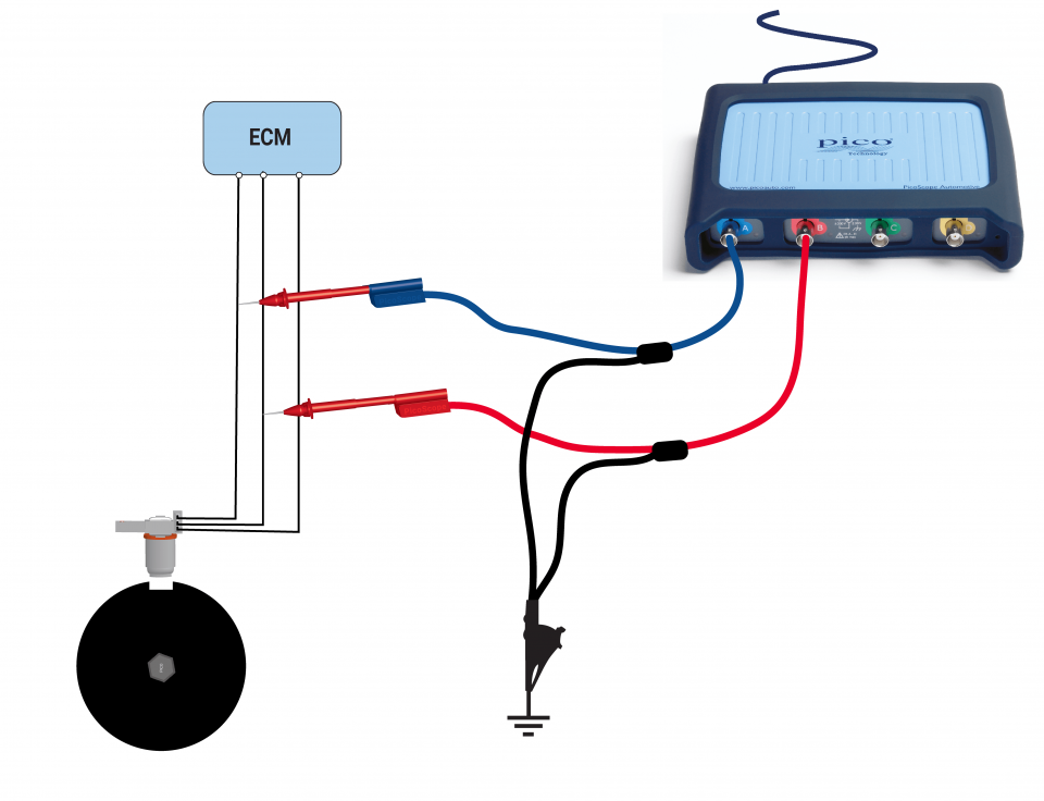
View connection guidance notes.
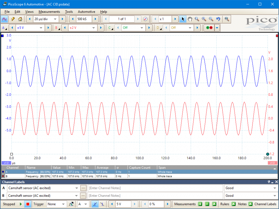
This camshaft sensor differs in operation from the other sensors by having an Alternating Current (AC) voltage supply. The ECM supplies a high frequency of around 100 to 150 kHz to an exciter coil that is located close to a rotating disc.
The disc is located at the end of the camshaft and has a section removed that, when aligned with the sensor, allows the frequency to excite the receptor (through mutual inductance). The signal returns to the ECM, indicating the position of number 1 cylinder.
Selection of component related Diagnostic Trouble Codes (DTCs):
P0340 : Camshaft Position Sensor A - Circuit Malfunction (Bank 1)
P0341 : Camshaft Position Sensor A - Circuit Range/Performance (Bank 1)
P0342 : Camshaft Position Sensor A - Circuit Low Input (Bank 1)
P0343 : Camshaft Position Sensor A - Circuit High Input (Bank 1)
P0344 : Camshaft Position Sensor A - Circuit Intermittent (Bank 1)
P0345 : Camshaft Position Sensor A - Circuit Malfunction (Bank 2)
P0346 : Camshaft Position Sensor A - Circuit Range/Performance (Bank 2)
P0347 : Camshaft Position Sensor A - Circuit Low Input (Bank 2)
P0348 : Camshaft Position Sensor A - Circuit High Input (Bank 2)
P0349 : Camshaft Position Sensor A - Circuit Intermittent (Bank 2)
P0365 : Camshaft Position Sensor B - Circuit Malfunction (Bank 1)
P0366 : Camshaft Position Sensor B - Circuit Range/Performance (Bank 1)
P0367 : Camshaft Position Sensor B - Circuit Low Input (Bank 1)
P0368 : Camshaft Position Sensor B - Circuit High Input (Bank 1)
P0369 : Camshaft Position Sensor B - Circuit Intermittent (Bank 1)
P0390 : Camshaft Position Sensor B - Circuit Malfunction (Bank 2)
P0391 : Camshaft Position Sensor B - Circuit Range/Performance (Bank 2)
P0392 : Camshaft Position Sensor B - Circuit Low Input (Bank 2)
P0393 : Camshaft Position Sensor B - Circuit High Input (Bank 2)
P0394 : Camshaft Position Sensor B - Circuit Intermittent (Bank 2)
GT013-5
Disclaimer
This help topic is subject to changes without notification. The information within is carefully checked and considered to be correct. This information is an example of our investigations and findings and is not a definitive procedure.
Pico Technology accepts no responsibility for inaccuracies. Each vehicle may be different and require unique test
settings.
We know that our PicoScope users are clever and creative and we’d love to receive your ideas for improvement on this test. Click the Add comment button to leave your feedback.


