PicoScope 7 Automotive
Available for Windows, Mac, and Linux, the next evolution of our diagnostic scope software is now available.
Automotive guided tests
Library of examples on how to perform tests when using PicoScope.

Training
Our collection of training videos, articles, guides and information on training courses.

Waveform library
The Waveform Library is a global database of waveforms uploaded by PicoScope users.

Case studies
Real-life case studies show how the professionals use PicoScope to diagnose vehicle faults.

A to Z of PicoScope
Detailed description of various PicoScope software and hardware features.

Videos
Training resources and demonstrations on PicoScope and the Automotive Diagnostics Kit.

Newsletter
Archive of our monthly Automotive Newsletters.

Documentation
Download manuals, brochures, posters, and training materials.

Reviews and awards
Accolades for the preferred diagnostic tool for service centers and vehicle manufacturers.

After completing a presentation at Autoinform Harrogate and a conversation with Pete Melville (HEVRA), I wanted to qualify the suggestion of using PicoScope ConnectDetect® to determine the cause of specific sensor faults.
Before I begin, you can find more information on the ConnectDetect feature in PicoScope here.
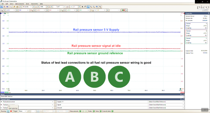
The PicoScope 4225 and 4425 models can display the status of your x1 test lead connection (e.g. to the component) based on the impedance of the circuit to which your test lead is connected. Therefore, you know when you have made a good connection to the component/circuit before starting a capture.
ConnectDetect functions with circuits of low impedance (resistances up to 100 kΩ)
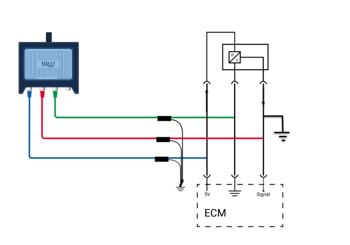
The images below illustrate how PicoScope is connected to a typical fuel rail pressure sensor circuit and the response from ConnectDetect when all the connections are good.
Now, let’s take this one step further. Imagine a fuel rail pressure sensor with a sporadic output. I think we can all agree there are numerous possibilities as to why. A typical fuel rail pressure sensor has a 5 V supply, sensor ground and a signal wire carrying a voltage that is dependent upon fuel pressure. Assuming the physical fuel pressure is good, but the sensor signal is corrupt, we could have:
Sensor supply wire intermittent open circuit
Sensor supply wire intermittent short to ground or + 12 V
Sensor signal wire intermittent open circuit
Sensor signal wire intermittent short to ground or + 12 V
Sensor ground wire intermittent open circuit
Sensor ground wire intermittent short to + 12 V
High resistance is another typical fault which must be considered when you use ConnectDetect as a fault-finding tool. While high resistance will increase the circuit impedance, if the total resistance remains below 100 kΩ (in the fault condition) it will inhibit the ability for ConnectDetect to conclusively identify the type of a fault condition (e.g. open circuit or short to ground).
The conversation between Pete and I suggested: “If ConnectDetect uses impedance of the circuit to determine connection status, could we use ConnectDetect to reveal the style of fault?”
This depends on several factors such as:
• Your measurement point with the circuit under test
• The influence upon circuit impedance based on the style of fault
• The behaviour of the circuit in response to one of the faults listed above. (Not all sensors and circuits behave in the same manner in response to these faults.)
• The ConnectDetect update speed, which is governed by the time base setting of the scope.
(The ConnectDetect status is updated at the end of each buffer, therefore status updates are received sooner on faster time bases).
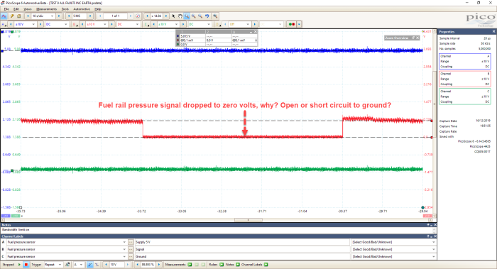
Let’s take a fuel rail pressure sensor with the signal voltage dropping to zero volts with the engine running. This could be due to numerous faults, but let’s assume that this is due to a momentary open circuit or a short to ground in the signal wire. Our initial assumption is that both fault conditions potentially generate identical symptoms. However, with the fuel rail pressure sensor circuit, the reality is completely different! With that said, could ConnectDetect be used to reveal the status of the circuit (open or short to ground) during the fault condition?
Theory
A short to ground has a low impedance and so ConnectDetect indicates the status of our connection as Green, whereas an open circuit has infinite resistance/impedance resulting in ConnectDetect indicating Red. As an end-user, you now have an understanding as to why the voltage has fallen to 0 V (style of fault) on the fuel rail pressure sensor signal wire.
Reality
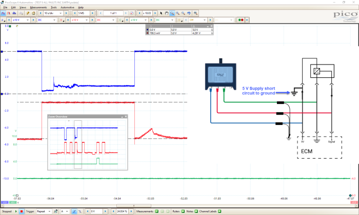
Figures 4 and 5 demonstrate the fuel rail pressure sensor signal wire shorted to ground (0 V), yet the status of ConnectDetect remains faded and green, indicating to the user that the circuit is not open and there must be an impedance with a resistance of less than 100 kΩ at the test lead signal wire. In other words, the test lead probe is still connected to the circuit and the circuit is not open.
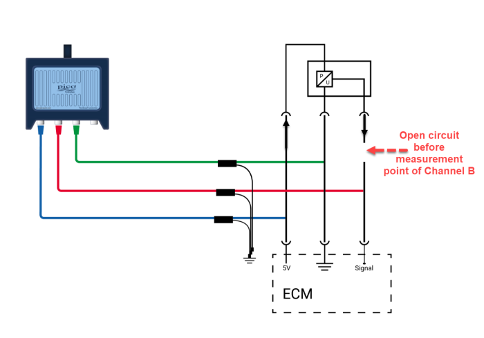
One variable to consider is the measurement point within the fuel rail pressure sensor circuit as this has a huge influence on the response of ConnectDetect.
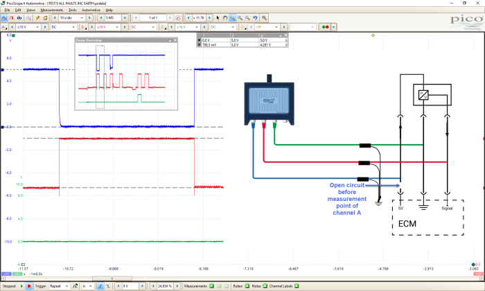
Below, we have an open circuit in the fuel rail pressure signal wire after the measurement point of the Channel B test lead.
Once again, there is no change in the status of ConnectDetect as the circuit impedance has not changed sufficiently to warrant an indication to the user. Notice we still have the correct voltage from the rail pressure sensor signal wire at idle speed, given that the open circuit is after the measurement point.
In the scenario above, the ECM would record a fault code for fuel rail pressure signal error and it would display such an error via live data. This demonstrates the need for probing sensor signals at the ECM and actuators at the components (such as EGR Valve Motor). Here, we incorporate the harness into our measurement, but this is not always possible in the real world.
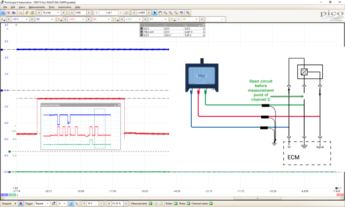
Next, we have an open circuit in the fuel rail pressure sensor signal wire before the measurement point.
Once again, there is no change in the status of ConnectDetect as the circuit impedance has not changed sufficiently to warrant an indication to the user. The tell-tale sign here is that our signal wire has now increased to 5 V, which is typical of an ‘open’ with this circuit/connection arrangement.
We have, therefore, covered two possible fault conditions (open and short to ground) with the fuel rail pressure signal wire, but with three different outcomes depending on your measurement point in the circuit. In all cases, ConnectDetect had no cause to indicate to the user that the connection of the test lead to the circuit under test had changed (which is correct).
What is more important, is that we have confirmed that, in this scenario, we cannot rely on ConnectDetect to inform the user of the style of fault, as we first thought in our initial conversation.
ConnectDetect, therefore, remains the perfect tool to verify your test lead connection to the circuit before measurement, and for any change to that connection during the capture (e.g. an unexpected disconnection of a test lead).
More fault combinations
Looking at the fuel rail pressure sensor circuit (Figure 1 above) I have included a short video covering open faults (before and after measurement points) in all three wires and shorts to ground within the 5 V supply and signal wires of this circuit.
These deliberate faults reveal the effects on the voltage in all three wires during the fault conditions and highlight the characteristic response of the circuit/ECM.
For example, with the engine running at idle speed, the 5 V sensor supply was opened before the measurement point on Channel A and then restored. It was then opened after the measurement point and restored, followed by the 5 V sensor supply being shorted to ground.
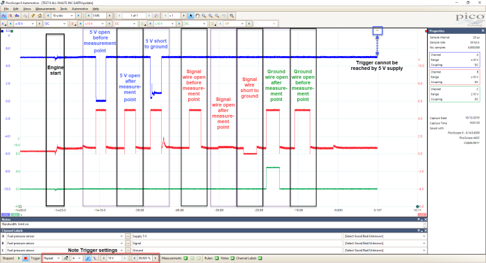
The following capture displays eight deliberate faults placed on the fuel rail pressure circuit and the response from each of the three wires. (Note that the sensor ground wire was not shorted to ground as it is already a ground reference via the ECM).
Notice how a long timebase (10 s/div) has been chosen (ConnectDetect is deactivated) along with a rising edge trigger point set at 10 V to measure the 5 V sensor supply on Channel A.
This is deliberate, as I do not expect the 5 V supply to ever reach this 10 V value. Hence the capture will scroll from right to left of the screen until the scope is stopped by the user. This technique is ideal for capturing those intermittent faults hands-free, as once you experience the glitch (for example on a road test) you will have the time it takes the capture/glitch to scroll from the right of the screen to the left (100 seconds) before the data is lost! (here we only ever capture a single buffer)
Remember once the glitch has left the screen (with these scope settings) it is lost forever, so make sure you stop and save the capture for review as soon as it is safe to do so.
Below we have the faults with their corresponding waveforms
5 V sensor supply is open before the measurement point.
The 5 V sensor supply is open before the measurement point:
The 5 V sensor supply is open after the measurement point:
The 5 V sensor supply shorted to ground:
The sensor ground is open after the measurement point:
The sensor ground is open before the measurement point:
Tips for using ConnectDetect