PicoScope 7 Automotive
Available for Windows, Mac, and Linux, the next evolution of our diagnostic scope software is now available.
Automotive guided tests
Library of examples on how to perform tests when using PicoScope.

Training
Our collection of training videos, articles, guides and information on training courses.

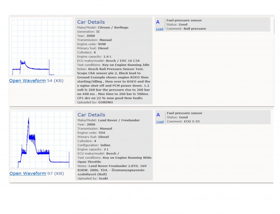
Waveform library
The Waveform Library is a global database of waveforms uploaded by PicoScope users.

Case studies
Real-life case studies show how the professionals use PicoScope to diagnose vehicle faults.

A to Z of PicoScope
Detailed description of various PicoScope software and hardware features.

Videos
Training resources and demonstrations on PicoScope and the Automotive Diagnostics Kit.

Newsletter
Archive of our monthly Automotive Newsletters.

Documentation
Download manuals, brochures, posters, and training materials.

Reviews and awards
Accolades for the preferred diagnostic tool for service centers and vehicle manufacturers.


Multimeter Probes

Back-pinning Probe Set

Large Dolphin/Gator Clips
*At Pico we are always looking to improve our products. The tools used in this guided test may have been superseded and the products above are our latest versions used to diagnose the fault documented in this case study.
The purpose of this test is to check the fuel system pressure characteristics on a common rail diesel engine by using the fuel rail pressure sensor.
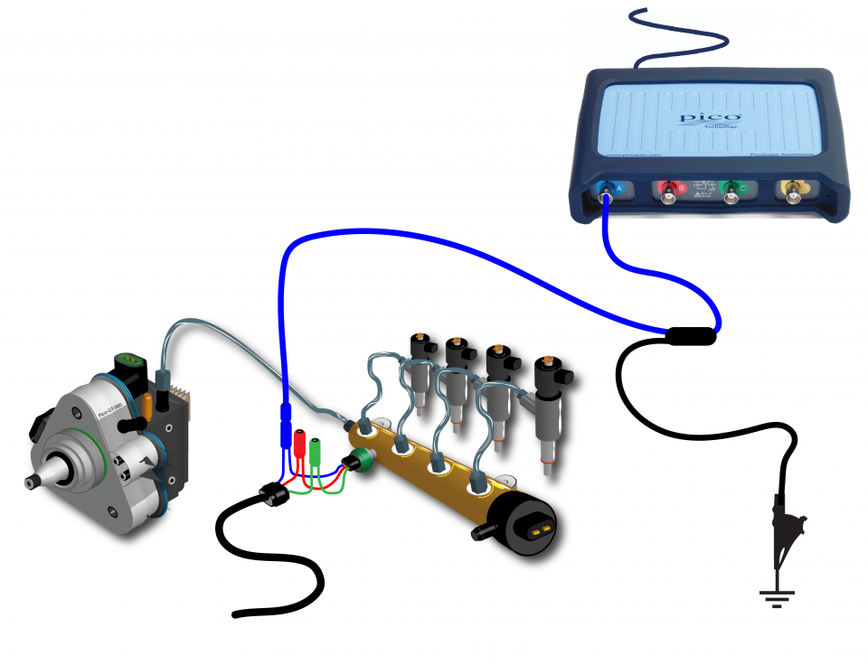
View connection guidance notes.
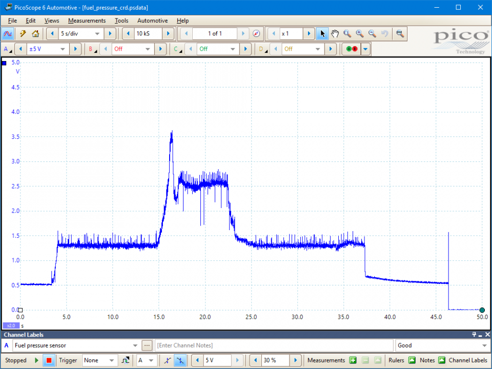
This known good waveform has the following characteristics:
Go to the drop-down menu bar at the lower left corner of the Waveform Library window and select Fuel pressure sensor.

The fuel rail pressure sensor provides feedback to the ECM, which regulates the rail pressure by varying the volume of fuel delivered by the high-pressure pump and/or controlling the flow of excess fuel from the rail to the fuel return system. The ECM uses its internal calibration tables (maps) to calculate the desired fuel rail pressure and injection duration according to the accelerator pedal position (indicating driver demand), engine speed, load, and temperature etc.
The rail pressure sensor is calibrated to output a signal between 0.5 V and 4.5 V with changing rail pressure across the range 0 bar to 1600 bar. This provides two opportunities for the ECM to undertake a signal plausibility check: any voltage above or below these values, for example, either at 0 V or 5 V, will indicate that the sensor has failed.
A high-pressure system leak can be indicated if the sensor output rapidly drops to 0.5 V after the engine has been stopped, as might occur with a leaky injector, rail pressure regulator, inlet metering valve or pump.
Please note, the example waveform was captured with an unloaded engine; with the engine fully loaded over a prolonged period, the sensor output voltage will be above 2.5 V and, in the extreme case, up to 4.5 V.
Selection of component related Diagnostic Trouble Codes (DTCs):
P0087 – Fuel rail pressure sensor or rail pressure too low
P0088 – Fuel rail pressure sensor or rail pressure too high
P0190 – Fuel rail pressure sensor circuit open/short/failure
P0191 – Fuel rail pressure sensor circuit performance/range
P0192 – Fuel rail pressure sensor circuit low input
P0193 – Fuel rail pressure sensor circuit high input
P0194 – Fuel rail pressure sensor circuit intermittent
GT138-EN
Disclaimer
This help topic is subject to changes without notification. The information within is carefully checked and considered to be correct. This information is an example of our investigations and findings and is not a definitive procedure.
Pico Technology accepts no responsibility for inaccuracies. Each vehicle may be different and require unique test
settings.
We know that our PicoScope users are clever and creative and we’d love to receive your ideas for improvement on this test. Click the Add comment button to leave your feedback.
Nav
November 29 2018
What faults would this test actually discover? Please give examples


