PicoScope 7 Automotive
Available for Windows, Mac, and Linux, the next evolution of our diagnostic scope software is now available.
Automotive guided tests
Library of examples on how to perform tests when using PicoScope.

Training
Our collection of training videos, articles, guides and information on training courses.

Waveform library
The Waveform Library is a global database of waveforms uploaded by PicoScope users.

Case studies
Real-life case studies show how the professionals use PicoScope to diagnose vehicle faults.

A to Z of PicoScope
Detailed description of various PicoScope software and hardware features.

Videos
Training resources and demonstrations on PicoScope and the Automotive Diagnostics Kit.

Newsletter
Archive of our monthly Automotive Newsletters.

Documentation
Download manuals, brochures, posters, and training materials.

Reviews and awards
Accolades for the preferred diagnostic tool for service centers and vehicle manufacturers.


Back-pinning Probe Set

Flexible Back-pinning Probe

Large Dolphin/Gator Clips
*At Pico we are always looking to improve our products. The tools used in this guided test may have been superseded and the products above are our latest versions used to diagnose the fault documented in this case study.
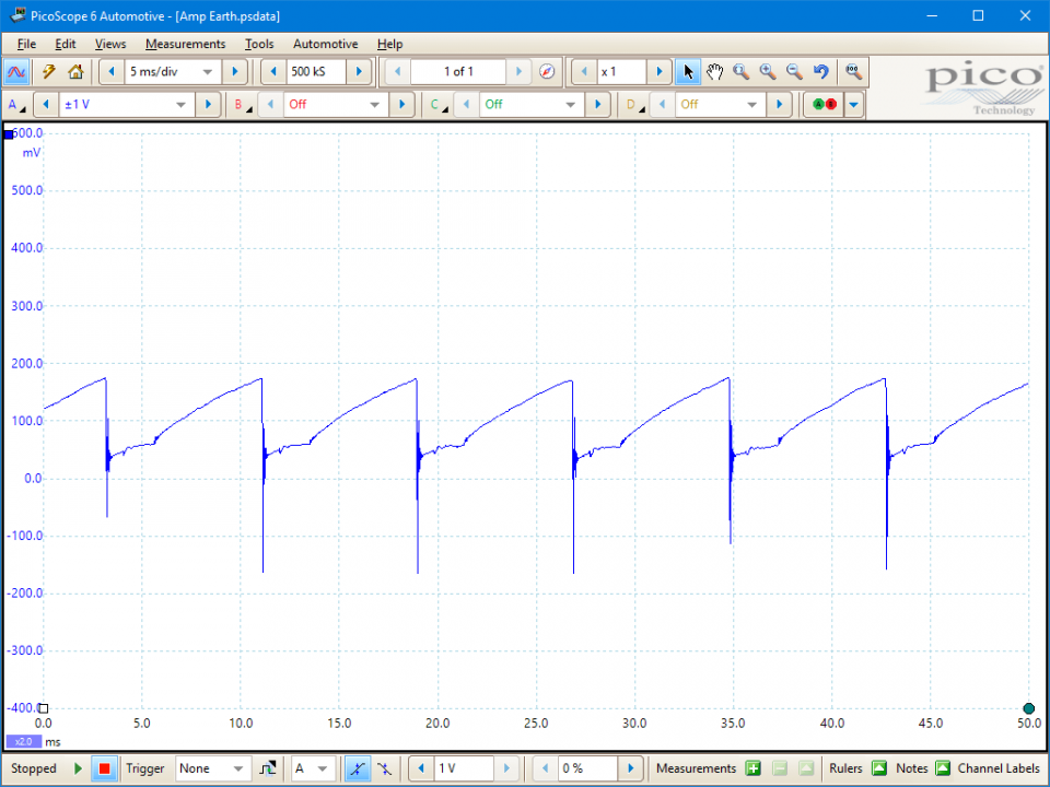
The purpose of this test is to evaluate the integrity of ignition amplifier ground circuit based on voltage levels during engine run conditions.

View connection guidance notes.
The earthing on the ignition amplifier (also referred to as the module or the igniter) is vital to the operation of the ignition system and is often overlooked as an area for potential problems.
The earth connection, if not in good condition, can cause a reduction in the primary current that will affect the current limiting (or dwell control) circuit. It is therefore vital that this important connection is tested and rectified if it is found to be outside of its operational limits. An earth return circuit can only be tested while the circuit is under load and this therefore makes continuity testing to earth with a multimeter inaccurate. As the coil's primary circuit is only complete during the dwell period, this is the time that the voltage drop should be monitored.
Ensure that the 'voltage ramp' does not exceed 0.5 volts. The 'flatter' the resultant waveform the better. A waveform with virtually no rise, shows that the amplifier/module has a perfect earth. If the 'ramp' is too high, another earth wire can be soldered in parallel with the original wire and secured to a good earthing point.

The purpose of the ignition amplifier is to switch the relatively high primary current of approximately 8 to 10 amps to earth, when the component receives a signal from either the pick-up or Electronic Control Module (ECM). The earth path on this circuit plays a very important role in maintaining the correct operation of the primary ignition circuit.
The earth path is often overlooked as a problem area, the condition of the wiring and connections to ground can be checked using the Ohms scale on a multimeter. However, the reading may indicate good continuity under these conditions (no load), but this test does not demonstrate the circuit's ability to perform while operational.
A volt drop check is the only option available if the earth's path back to the battery is to be correctly assessed. When checking using an oscilloscope, the flatter the resultant waveform the better as this ensures a good earth path to the coil, through the amplifier. The length of the ramp is determined by the dwell angle and will expand as the engine speed increases.
GT041
Disclaimer
This help topic is subject to changes without notification. The information within is carefully checked and considered to be correct. This information is an example of our investigations and findings and is not a definitive procedure.
Pico Technology accepts no responsibility for inaccuracies. Each vehicle may be different and require unique test
settings.
We know that our PicoScope users are clever and creative and we’d love to receive your ideas for improvement on this test. Click the Add comment button to leave your feedback.


