PicoScope 7 Automotive
Available for Windows, Mac, and Linux, the next evolution of our diagnostic scope software is now available.
Automotive guided tests
Library of examples on how to perform tests when using PicoScope.

Training
Our collection of training videos, articles, guides and information on training courses.

Waveform library
The Waveform Library is a global database of waveforms uploaded by PicoScope users.

Case studies
Real-life case studies show how the professionals use PicoScope to diagnose vehicle faults.

A to Z of PicoScope
Detailed description of various PicoScope software and hardware features.

Videos
Training resources and demonstrations on PicoScope and the Automotive Diagnostics Kit.

Newsletter
Archive of our monthly Automotive Newsletters.

Documentation
Download manuals, brochures, posters, and training materials.

Reviews and awards
Accolades for the preferred diagnostic tool for service centers and vehicle manufacturers.


Multimeter Probes

Back-pinning Probe Set

Flexible Back-pinning Probe

PicoScope Battery Clip
*At Pico we are always looking to improve our products. The tools used in this guided test may have been superseded and the products above are our latest versions used to diagnose the fault documented in this case study.
The purpose of this test is to check the output from a digital Air Flow Meter (AFM).

View connection guidance notes.
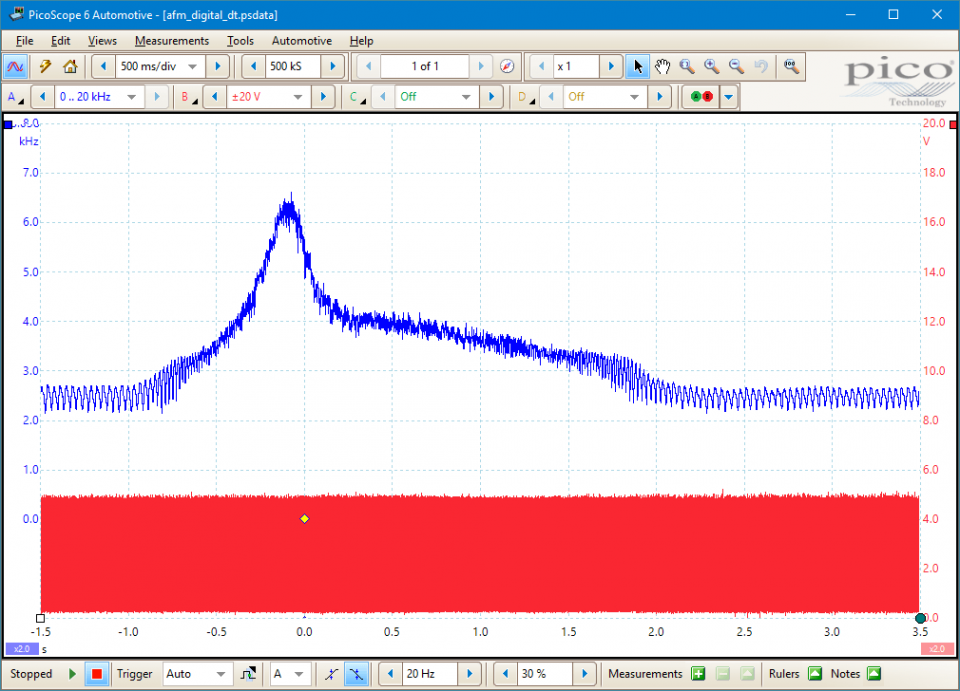
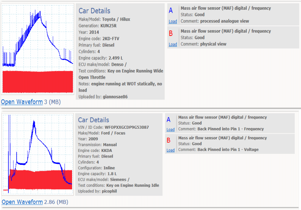
These known good waveforms have the following characteristics:
Go to the drop-down menu bar at the lower left corner of the Waveform Library window and select, Mass air flow sensor (MAF) digital / frequency.

Air flow meters measure the quantity of filtered air entering an engine. As such, they are used by the Engine Control Module (ECM) as the primary engine load sensor.
Digital air flow meters operate in a manner similar to hot-wire (or film) air flow meters but have a digital signal output. The digital signal is not affected by noise and interference in the same way as an analog signal, which improves its integrity.
Furthermore, the scaling and corrections required to convert the signal to an accurate representation of air flow are made within the meter and the subsequent output does not require analog-to-digital conversion. Both these factors reduce the complexity and therefore cost of the ECM.
As the digital signal is represented by only two voltage levels, the voltage amplitude does not indicate the air flow. Instead, the air flow is indicated by the varying frequency of the digital signal.
When testing a digital air flow meter, the output signal must be correctly identified: these units often measure both air flow and intake air temperature and give each a digital output. At first glance, the digital air temperature signal is similar to the air flow signal; however, the former is often a pulse-width modulated (PWM) waveform with a fixed cycle rate of around 20 kHz.
The sensor element and air flow meter body form a calibrated unit and are not interchangeable.
Bosch HFM6 digital air flow meters can be reliably tested with still air conditions, ignition on, engine off and exhaust extraction systems removed.
Under these conditions the signal frequency must be between 1.76 and 1.93 kHz. A measurement outside of this range indicates a faulty sensor.
Selection of component related Diagnostic Trouble Codes (DTCs):
P00BC Mass or Volume Air Flow "A" Circuit Range/Performance - Air Flow Too Low
P00BD Mass or Volume Air Flow "A" Circuit Range/Performance - Air Flow Too High
P00BE Mass or Volume Air Flow "B" Circuit Range/Performance - Air Flow Too Low
P00BF Mass or Volume Air Flow "B" Circuit Range/Performance - Air Flow Too High
P0100 Mass or Volume Air Flow "A" Circuit Malfunction
P0101 Mass or Volume Air Flow "A" Circuit Range/Performance Problem
P0102 Mass or Volume Air Flow "A" Circuit Low Input
P0103 Mass or Volume Air Flow "A" Circuit High Input
P0104 Mass or Volume Air Flow "A" Circuit Intermittent
P010A Mass or Volume Air Flow "B" Circuit
P010B Mass or Volume Air Flow "B" Circuit Range/Performance
P010C Mass or Volume Air Flow "B" Circuit Low
P010D Mass or Volume Air Flow "B" Circuit High
P010E Mass or Volume Air Flow "B" Circuit Intermittent/Erratic
GT095
Disclaimer
This help topic is subject to changes without notification. The information within is carefully checked and considered to be correct. This information is an example of our investigations and findings and is not a definitive procedure.
Pico Technology accepts no responsibility for inaccuracies. Each vehicle may be different and require unique test
settings.
We know that our PicoScope users are clever and creative and we’d love to receive your ideas for improvement on this test. Click the Add comment button to leave your feedback.


