PicoScope 7 Automotive
Available for Windows, Mac, and Linux, the next evolution of our diagnostic scope software is now available.
Automotive guided tests
Library of examples on how to perform tests when using PicoScope.

Training
Our collection of training videos, articles, guides and information on training courses.

Waveform library
The Waveform Library is a global database of waveforms uploaded by PicoScope users.

Case studies
Real-life case studies show how the professionals use PicoScope to diagnose vehicle faults.

A to Z of PicoScope
Detailed description of various PicoScope software and hardware features.

Videos
Training resources and demonstrations on PicoScope and the Automotive Diagnostics Kit.

Newsletter
Archive of our monthly Automotive Newsletters.

Documentation
Download manuals, brochures, posters, and training materials.

Reviews and awards
Accolades for the preferred diagnostic tool for service centers and vehicle manufacturers.

Research into the operation of a 3-phase permanent magnet synchronous motor/generator (MG), that had been fitted to a VW E-Golf, raised several questions surrounding the typical operation and circuit characteristics. I would like to share and discuss these questions and findings here.
Before we proceed, bear in mind that safety, certification, training and system knowledge are both essential and paramount as the captures below include live working.
Regarding system knowledge, the following Self Study Programs (SSP-530 & SSP-527) from VAG provide an invaluable insight into the description and operation of the high-voltage system onboard the E-Golf.
N.B. SSPs are not substitutes for EV training.
Let me start with an overview of the circuits I measured. The screenshot below shows our E-Golf pulling away from rest and then decelerating to a stop with “recuperation” level 3 activated (selectable by the driver). I.e., the vehicle is decelerating thanks to the “loading” of the “rotor”, which functions as a generator. (The rotor is connected to the road wheels via the transmission.)

During the test above, we had a question surrounding MG status: “How can we determine, from the recent captures, when the MG functions either as a motor or a generator?”
I guess the simple answer has to be the HV battery DC current captured on Channel F. We have captured the precise point where the current flow from the HV battery changed from a positive value (powering the motor) to a negative value thanks to regeneration from the MG now functioning as a generator (see below).

Note how the positive DC current flows from the HV battery peaks at approx. + 91 A in the screenshot above. This is to power our motor and drive the vehicle. During deceleration, the current flow is reversed thanks to our MG acting as a generator, leading to a peak negative current flow of approximately –50 A.
Around 12.5 seconds into our capture, another -16 A of current is delivered to the HV battery (a total of -66.85 A), thanks to the application of the brake pedal providing an additional reduction in rotor speed and a further increase in the generation of current.
Just a quick tip here: Note how Channel F has four signal rulers instead of two!
To use four signal rulers for one waveform, you have to create a reference waveform that automatically hides behind the waveform of interest. The benefit of duplicating a waveform is the additional two signal rulers that provide a means for multiple measurements of the same trace.
For more information about reference waveforms, I recommend that you refer to the A to Z of PicoScope here and here.
To understand the performance of our MG when it is acting as a generator, you can take a deeper dive into the operational characteristics of a 3-phase permanent magnet synchronous motor from the PicoScope data above and the theory below.
The following forum post discusses the operation of a 3-phase, brushless, DC motor, which (for want of a better description) is exactly what we have in the vehicle in question.
Rather than me trying to explain how the 3-phase brushless DC motor functions you could take a look at the superb animation here. Please note that in this animation the rotor is on the outside of the stator. With EV applications, the rotor is placed inside the stator and is ultimately connected to the road wheels.
To summarize the operation described in the animation above, a rotating magnetic field (RMF) is generated in the stator of our MG and referred to as “electronic commutation” or “EC” for short.
The speed of the RMF is governed by the precise switching of multiple Power Transistors using PWM control signals.
The desirable side effect of precise switching (PWM control) of HV DC current is the creation of a 3-phase HV AC current.
The following video covers the conversion of DC to AC in greater detail.
By using the positive duty cycle of channel E below, we can see how the high voltage of one of our MG phases (Phase W) is controlled to create the AC current.

Note that the math channel above, “posduty(E)”, reveals how the peak positive duty control of MG Phase W voltage (approximately 58%) nearly coincides with the peak positive current flow (approximately 171 A) through the phase winding. Likewise, our lower positive duty of 42% is near to coincide with our peak negative current of -177 A.
Note where the positive duty math channel in the screenshot below also reveals how the voltage leads the current (by approx. 469 µs), which is typical of an inductor and highlights the inherent properties of a wire coil (phase W) that oppose AC current flow due to inductive reactance.

Now we have our RMF (whose rotational speed is known as synchronous speed) we can now initiate rotation of the rotor and of course the road wheels thanks to the interaction between the induced magnet field of the stator and permanent magnet rotor. Once again please refer to the animation and video links above.
The theoretical speed of the rotor within a synchronous motor should be identical to the RMF of the stator (after all this is a synchronous motor) We can prove this theory using math’s and the formulas below to discover clues to the status of our MG. Is it acting as a motor or as a generator based on rotor speed?
So how do we calculate RMF and rotor speeds?
Let us start with RMF speed calculation. We can use the following formula: 120*Freq(C) / Number of poles.
120 refers to the degrees of separation between our three phases (120°).
Frequency (C) refers to the frequency of the AC current (Hz) through our phases.
The number of poles refers to the number of magnets x 2 to derive the pole count (each magnet has a north and south pole).
After referring to our SSPs once more, it appeared that our rotor had five magnetic pole pairs (ten poles) and I assumed it was the same for the stator!
In the screenshot below are using the math channel “120*freq(C)/10” to display the speed of our RMF (synchronous speed).

We had several alternatives for defining the rotor speed, and my first choice was to use wheel speed multiplied by the transmission ratio.
This is where our optical pick up (on Channel B) aimed at a piece of reflective tape attached to the left-hand drive shaft will generate one pulse per revolution of the road wheel.
To improve resolution and accuracy, I then added the wheel speed sensor signal of the L-H front wheel on Channel A.
By using the single pulse from the driveshaft, we can now calculate the number of pulses from our wheel speed sensor in relation to one revolution of the road wheel. We have used this technique previously and you can read about it here.

By using the “Falling Edge Count” measurement feature in PicoScope 7 Automotive (between the time rulers in the screenshot above) we can conclude that our ABS wheel speed sensor “pick-up” returned 44 pulses per revolution.
Because we knew that the transmission of the E-Golf contains a single gear ratio of 2.704:1 and a final drive ratio of 3.608, our total overall gear ratio is equal to 2.704 x 3.608 = 9.756 :1
We can now calculate rotor speed using the following math channel: (60/44*freq(A)/60)*9.756*60
60/44*freq(A) will provide the RPM of the road wheel based on 44 pulses per revolution from the ABS sensor.
/60 will convert rpm to the frequency in Hz.
*9.756 will return the frequency of the rotor in Hz.
*60 will convert rotor frequency to RPM.

As you can see in the screenshot above, the rotor speed we calculated from the ABS wheel speed and total transmission ratio appeares to be lower than the synchronous speed! This is in stark contrast to the characteristics of a synchronous motor and highlights the variables that need to be considered when we calculate rotor speed in this fashion. Typical variables include a build-up of tolerances throughout the drivetrain and differential action due to steering deviation, etc.
An alternative option to measure rotor speed would be to use the integrated rotor speed sensor (referred to by VAG as “G713”).
To do this, we need to determine the number of electrical cycles from the rotor's speed sensor in relation to one revolution of the rotor, but how?
This requires knowledge of the rotor pole count as described in our SSPs 530 and 527 which in this case, as I mentioned earlier, is ten. The pole count is then divided by two to determine the number of electrical cycles for one revocation of the rotor. But why divide by two?
The ten rotor poles are arranged alternatively: North, south, north, south, etc. As each pole is detected by the speed sensor (e.g., a north pole), it generates a voltage output in the respective direction, creating one half of our sine wave. As the following alternate pole (e.g., a South pole) is detected by the speed sensor, it generates a voltage output in the opposite direction, creating the second half of our sine wave and completing one electrical cycle. Hence for every complete electrical cycle, two alternate magnetic poles must have passed by the rotor speed sensor.
Therefore, the number of electrical cycles per rotor revolution = Number of rotor poles (10) / 2 = 5.
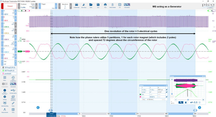
The following waveform will help clarify the statement above. Note, with this vehicle, the electrical cycles of the rotor speed sensor and rotor assembly are identical.

Based on the above: If we know the pole count of our rotor, we can use the formula 60/5*freq(H). Channel H is connected to the rotor speed sensor.
I think we can all agree that in the lime green math channel above, our rotor speed does indeed equal our RMF speed during acceleration and deceleration. We have now confirmed that this motor is, indeed, synchronous.
Graphing both RMF and rotor speeds across all rpm and load ranges (with synchronous MGs) will provide invaluable data when it comes to evaluating invertor performance, stator integrity, rotor balance and drivetrain condition. Here we are looking for uniformity and perfect synchronization between the two math channels where any “drop out” or cyclic deviation will highlight areas of concern. On the subject of cyclic deviation, check out Ben’s “Martins’ Method”.
Had this been an inductive asynchronous motor, our RMF speed would have been higher than the rotor speed during the acceleration but slower than the rotor speed during the deceleration (a phenomenon known as “slip”). This phenomenon/characteristic can be used as an indication of MG status (Motor or Generator) for inductive asynchronous motors only, which is nice to know, but this does not apply with our synchronous motor. So where to now?
Let me get back to the original question: “How can we determine, from the above captures, when the MG is functioning either as a motor or a generator?” Assuming you don’t have a current clamp around the HV battery DC cable (Image 2 above) and you are measuring a single-phase voltage (ref to HV negative) with current, the answer is “phase”.
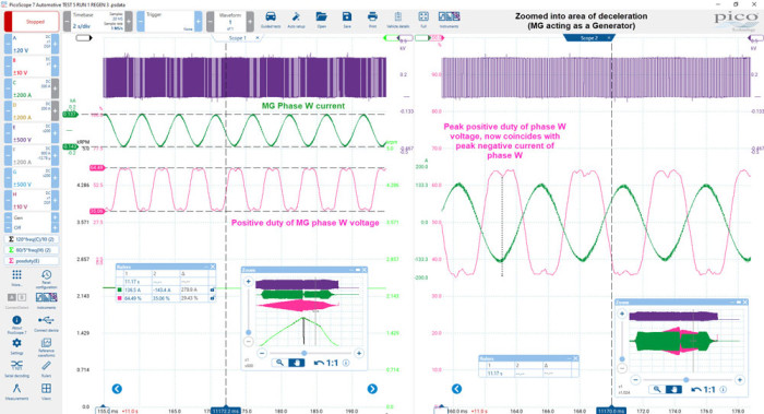
Note the phase relationship between the positive duty of the phase voltage and current in the screenshot below, compared to images 3 and 4 above.
Note above, how the math channel “posduty(E)” reveals how the peak positive duty control of MG Phase W voltage (approximately 64%) coincides with the peak negative current flow (approximately -143 A) through the phase winding. Likewise, our lower positive duty of 35% coincides with our peak positive current of -137 A. This is the complete opposite of the duty cycle behaviour when our MG is acting as a motor, as their phase relationship has shifted by approximately 180°! (Referring to electrical cycles).
The waveform below introduces the phase rulers to denote 360° of rotor rotation with five partitions, one for each rotor magnet (72° degrees apart). We can clearly see the phase shift between the positive duty of the phase voltage and current.

Since the relationship (“phase”) between the positive duty of our phase winding voltage and current reveals the operation status of the MG (motor or generator), wouldn’t it be great if we could simply graph phase shift rather than having to zoom into each section of the waveform and measure the phase?
Well, get ready for the mother of all math channels thanks to my colleague Martyn (the Obi-Wan of math channels):
LowPass(Duty(((((atan(1/tan(pi*((posduty(E)-50)/10000)))/pi)+((posduty(E)-50)/10000))*-((atan(1/tan(pi*(C/10000)))/pi)+(C/10000)))+0.25))/0.555555555,10)
I am not going to attempt to explain the above maths other than it contains a low pass filter, trigonometry, positive duty calculations and a sprinkle of magic!
Unfortunately, when applying this math channel to the capture above, it fails to draw any data due to a measurement error on Channel C! The keen-eyed will have spotted that during acceleration and deceleration there is an “over range” condition where the current flow has exceeded 200 A. In such a scenario, the maths channel cannot perform calculations and returns an infinite value resulting in no drawn data.
No need to worry, though, as a search through similar tests with the E-Golf turned up “TEST 8”, which has another acceleration and deceleration event with all phase currents within range and with the added benefit of HV battery DC voltage. (Note the increase during deceleration.)
The math channel is now modified and we are looking at the phase between Channel A (phase winding U Voltage positive duty) and Channel D (phase winding U current): LowPass(Duty(((((atan(1/tan(pi*((posduty(A)-50)/10000)))/pi)+((posduty(A)-50)/10000))*-((atan(1/tan(pi*(D/10000)))/pi)+(D/10000)))+0.25))/0.555555555,10)
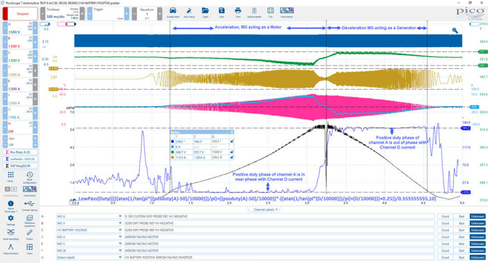
In the screenshot above, you can see how we graph the phase shift between the positive duty of our phase-winding U voltage (referenced to HV negative) and our phase winding U current to determine the status of our motor or generator (MG).
In the screenshot below, I have hidden some waveforms and removed numerous rulers to better demonstrate the value of graphing the phase shift.
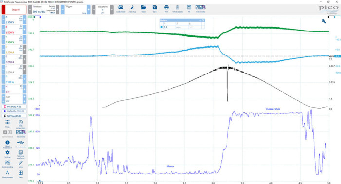
I hope this helps. There will be more to follow as we dig deeper into the captures from this article and compare the results with an inductive asynchronous motor. We have so much to learn together.


