PicoScope 7 Automotive
Available for Windows, Mac, and Linux, the next evolution of our diagnostic scope software is now available.
Automotive guided tests
Library of examples on how to perform tests when using PicoScope.

Training
Our collection of training videos, articles, guides and information on training courses.

Waveform library
The Waveform Library is a global database of waveforms uploaded by PicoScope users.

Case studies
Real-life case studies show how the professionals use PicoScope to diagnose vehicle faults.

A to Z of PicoScope
Detailed description of various PicoScope software and hardware features.

Videos
Training resources and demonstrations on PicoScope and the Automotive Diagnostics Kit.

Newsletter
Archive of our monthly Automotive Newsletters.

Documentation
Download manuals, brochures, posters, and training materials.

Reviews and awards
Accolades for the preferred diagnostic tool for service centers and vehicle manufacturers.

Pressure compensation
Until the arrival of the pressure transducer, peak cylinder pressure was our primary concern when measuring engine compression.
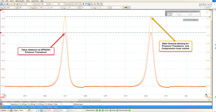
With the WPS500X on the scene, we are introduced to superior cylinder pressure analysis in the form of positive/negative cylinder pressures, valve open/close events and valve duration, to name but a few.
What soon becomes apparent is the discrepancy between peak cylinder pressures when measured by a traditional compression gauge, compared to the WPS pressure transducer.
This forum topic covers this well.
The internal volume of our pressure sensor (sensor volume) must be considered and compensated for if we require an accurate peak cylinder compression values captured with the pressure transducer.
Therefore, I wanted to revisit the maths involved when dealing with “Compensation” during the measurement of peak cylinder pressure with a pressure transducer and PicoScope (not PicoDiagnostics).
Here is an occasion where our users are right and my theory was wrong (not the first time this has happened).
I have, in the past, incorrectly assumed that our pressure transducer has an internal volume of 5 ml, but thanks to PicoKev, Volrem and others, we now know that the internal volume of the pressure transducer alone is approximately 1.22 ml.
If we then add our compression hose to the pressure transducer (with an approximate internal volume of 2 mL), we have a total of approximately 3.22 ml.
Add to this the internal volume of a compression hose adapter (for spark plug replication), and we have an average of 5 ml to cover the internal volume of the transducer, compression hose and spark plug adapter.
This is a “one size fits all” sensor volume measurement for petrol engine compression testing.
Remember that this will increase dramatically when we add a dummy glow plug (diesel compression testing) which can vary in size and, therefore, volume.
Basically what I am trying to say here is:
For peak compression measurements in petrol engines with the pressure transducer, use 5 ml as your sensor volume value when applying the relevant math channel.
For peak compression measurements in diesel engines with the pressure transducer, use 5 ml plus the volume of your dummy glow plug as your sensor volume value when applying the relevant math channel.
This forum topic states:
When using PicoScope 6 Automotive software, to measure peak cylinder pressure with a pressure transducer coupled to a compression hose (internal volume 5 ml) we need to calculate a multiplication factor based upon the cylinder volume, compression ratio and sensor volume value.
Here we have a Vauxhall Astra Diesel, 1.7 Litre, 4-cylinder engine with a compression ratio of 18:1 using a sensor volume value of 7 ml (transducer and compression hose 5 ml + 2 ml for our dummy glow plug).
Compensation formula required when using the WPS500x Pressure Transducer to measure peak cylinder pressure with PicoScope 6 Automotive software:
Cylinder displacement / (Compression Ratio -1) = Combustion chamber volume
Combustion chamber volume + Sensor volume value / Combustion chamber volume = Multiplication Factor
The Multiplication factor is then used to multiply the pressure results obtained by the WPS500X.
4-cylinder engine displacement 1686 cc, compression ratio 18:1
1686 / 4 = 421.50 cc Displacement per cylinder
421.50 cc / (18 -1) = 24.79 cc Combustion chamber volume
24.79 cc + 7 ml / 24.79 cc = 1.28
1.28 is the Multiplication factor required to correct peak cylinder pressure.
Multiplication factor x Obtained pressure = Correct peak cylinder pressure; allowing for the internal volume of the Pressure Transducer, compression hose and dummy glow plug.
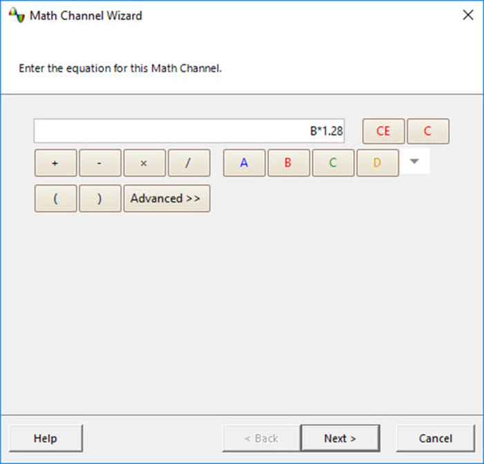
Math channel for WPS cylinder pressure captured on channel B:
Pressure x Multiplication factor = B X 1.28
Now, we have corrected the peak cylinder pressure value.
Be aware that temperature will also affect our compensation values. Temperature can be incorporated into alternative formulas if required.
You can download the psdata file I used for this example, including the compensation math channel here: Example waveform.psdata
Since the maximum operating pressure of the WPS500X is 34.5 bar (500 psi), there may be times when diesel engine cylinder pressure will exceed this value (especially if the injector remains connected during the compression test).
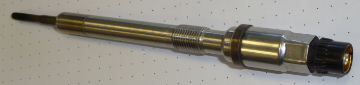
While the following is not applicable to all engines, we could take advantage of pressure transducers that are integrated into glow plugs.
Now we can measure peak cylinder pressure with combustion across all engine speeds and loads without intrusion and without increasing the volume of the combustion chamber.
The following formula applies to the pressure transducer incorporated into the glow plug of a current VAG TDI engine.
With thanks to VAG regarding an approximation of the specifications for this sensor, we can create a math channel that converts the measured voltage from the glow plug (pressure transducer) into a pressure value (bar).
The formula required:
Pressure = (Sensor Measured Voltage – Nominal Sensor Voltage) / Sensor Incline or slope
The sensor measured voltage = Voltage output from sensor in proportion to cylinder pressure
Nominal sensor voltage = Voltage output from sensor at ignition on engine off (0 bar) approximately 0.575 V
Sensor incline or slope refers to the characteristic output of the sensor across its entire operation range (0-210 bar) in response to cylinder pressure (1 V = Approx. 55.555 bar)
Think of this value as similar to a current clamp with a specified characteristic output of 1 mV/A. For every mV output of the current clamp, the scope display reads 1 A, therefore a 1 V output from the clamp (1000 mA) the scope display reads 1000 A.
Be aware, the sensor incline (or slope) is a rounded approximation which is dependent upon the pressure sensor supply voltage (ratiometric). Here we assume the sensor is supplied with 5 V, but in the real world this could deviate from 4.8 V to 5.2 V, etc., and this most certainly impacts upon the behaviour of the pressure sensor across its operating range. Consider the pressure values obtained from your math channel as relative cylinder pressure.
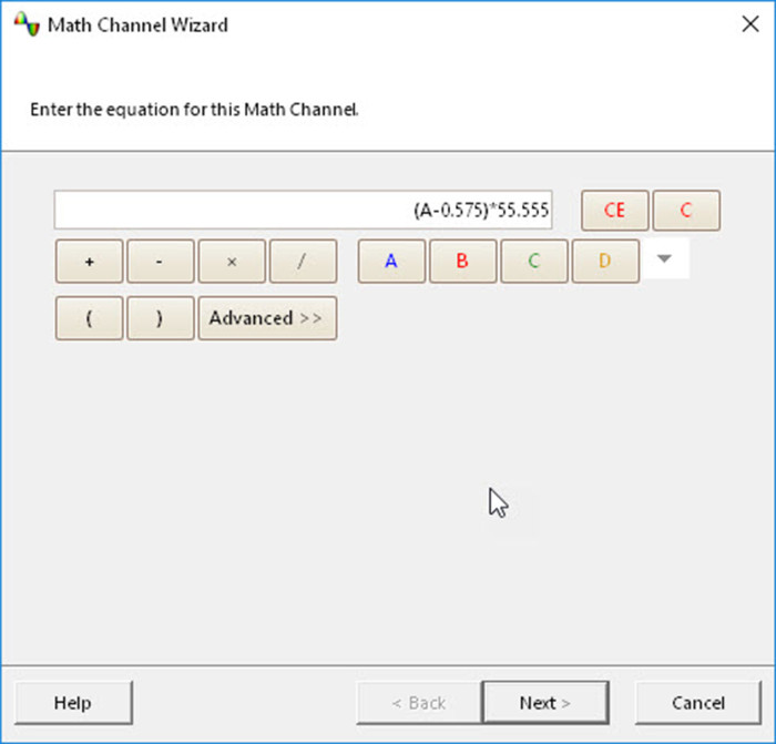
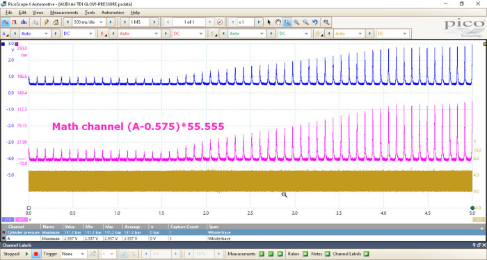
The math channel (assuming your glow plug pressure sensor is connected to channel A) is:
(A-0.575)/55.555
The waveform below highlights the dramatic increase in cylinder pressure under acceleration of the engine. This certainly brings home the “events” taking place inside the cylinder during combustion and reveals the stresses these engines are placed under during a typical driving cycle.
Please be aware of the limitations of the glow plug pressure sensor at low engine speeds/pressures given that the sensor is designed to measure pressure up to 210 bar. The resolution is also questionable but certainly invaluable for an insight into combustion events across the entire engine speed/load range.
The psdata file below contains the relevant math channel along with pressure waveforms from cylinders 2 and 4. These can be revealed by right-clicking on the screen and selecting “Channels”.
You can download the psdata file I used in this example here: AUDI A4 TDI GLOW-PRESSURE.psdata