PicoScope 7 Automotive
Available for Windows, Mac, and Linux, the next evolution of our diagnostic scope software is now available.
Automotive guided tests
Library of examples on how to perform tests when using PicoScope.

Training
Our collection of training videos, articles, guides and information on training courses.

Waveform library
The Waveform Library is a global database of waveforms uploaded by PicoScope users.

Case studies
Real-life case studies show how the professionals use PicoScope to diagnose vehicle faults.

A to Z of PicoScope
Detailed description of various PicoScope software and hardware features.

Videos
Training resources and demonstrations on PicoScope and the Automotive Diagnostics Kit.

Newsletter
Archive of our monthly Automotive Newsletters.

Documentation
Download manuals, brochures, posters, and training materials.

Reviews and awards
Accolades for the preferred diagnostic tool for service centers and vehicle manufacturers.

Following on from our video about the PicoBNC+ resistance lead for the 4425A scope, a question was raised regarding the possibility of measuring resistance with the 4425 Scope.
This is most certainly possible. We have to know the circuit we are measuring, capture the voltage and current flow (under load) and use Ohm's Law to calculate the resistance.
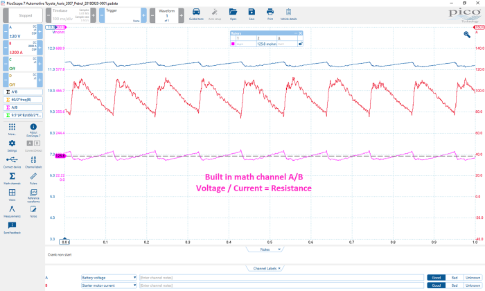
Below is a typical example. We are looking at the starter motor voltage and current from the very first Maths is Cool article here.
Resistance measurements like these are fine where the circuit is complete and both voltage and current are present under load. But what about measuring the resistance of a component removed from a circuit?
You can achieve this by creating your own voltage divider circuit in conjunction with the PicoScope.
In the example below I have used a 10 kΩ panel mount resistor (rated at 25 W) and a 12 V power supply (13.81 V to be precise).

Channel A is measuring the supply voltage, with reference to ground, before the 10 kΩ, 25-watt resistor (the supply).
Channel B is measuring the voltage across our unknown resistor, “R” (V2)
Using our knowledge of resistors in series (10 kΩ and R), keep in mind that they have the same current flow, but that the voltage divides.
It is equally important to keep In mind that the sum of all partial voltages (V1 and V2) is equal to the total voltage (the supply).
By utilizing math channels, we can now work out the missing values V1 and R.
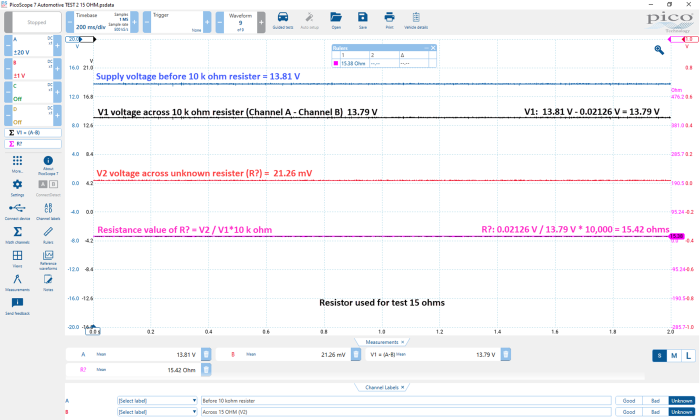
In the capture above, a 15-ohm resistor was placed between the signal and ground wires of the test lead connected to Channel B. This 15-ohm resistor was correctly measured and identified with PicoScope, confirming it is possible to measure and graph component resistance when they are removed from the circuit.
In the following capture, we have replaced the 15-ohm resistor with a 2200-ohm resistor and have correctly identified this value using math channels.

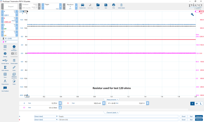
In this next capture, we replaced the 2200-ohm resistor with a 120-ohm resistor.
And in this capture, the 120-ohm resistor was replaced with a 0.1-ohm resistor.

While the examples above perform exceptionally well with the resistors we’ve used, there is a trade-off as the chosen component resistance (R) increases (when using this style of voltage divider circuit).
The method I’ve described will be sufficient for measuring component resistance up to approximately 50 kΩ. Any higher and the accuracy of the measurement will be affected due to the impedance of the scope in parallel with our voltage divider circuit.
We could overcome the accuracy concern by using a math channel to plot V2/V1 while measuring known resistor values from 0.1 KΩ, 10 KΩ, 100 KΩ and 1 MΩ and then create a custom probe to reflect these values. This will most certainly return accurate values at these chosen resistor values, but the accuracy between 100 KΩ and 1 MΩ would be compromised.
All these concerns, however, have been removed for users of the 4225A and 4425A scopes as the math’s, accuracy and scaling at all resistance levels are taken care of when you use the intelligent resistance lead.
You can create a resistance lead for your scope using a project box housing and a 10 kΩ resistor with 4 mm banana plugs to ease connectivity for the end-user. If you do this, you need to be aware that you need the current to flow through the voltage divider circuit to calculate the resistance (R), and where there is current flow, we must consider the power rating (wattage) of the resistor.
Power = I * V or V²/R
Consider a closed circuit at R (zero resistance)
13.81 V / 10,000 Ω = 0.001381 A (1 mA)
Power = 13.81 V x 0.001381 A = 0.01907161 watt (19 mW)
or
Power = 13.81 x 13.81 / 10,000 = 0.01907161 watt (19 mW)
Using a wire wound panel mount resistor rated at 25 W is fine (overkill), but the temptation to use a lighter and cheaper resistor will be hard to resist. However, power handling will be a compromise.
Likewise, using a smaller resistor than 10 kΩ could be an option but remember that if you halve the resistance you double the current!
For example, using a 5 kΩ resistor:
Consider a closed circuit at R? (Zero resistance)
13.81 V / 5,000 Ω = 0.002762 A (2 mA)
Power = 13.81 V x 0.002762 A = 0.03814322 watt (38 mW)
or
Power = V²/R=(13.81²)/5000 = 0.03814322 watt (38 mW)
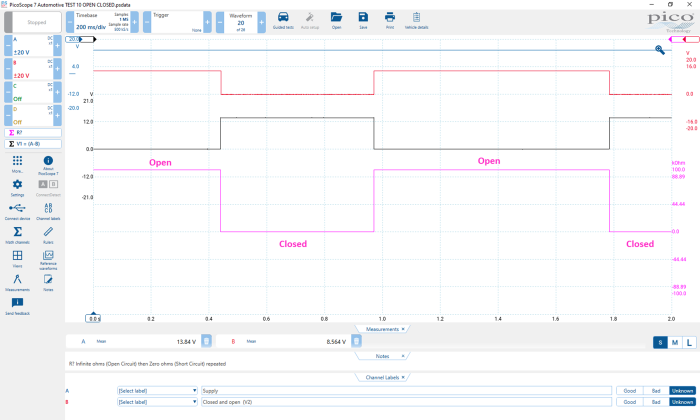
Finally, be aware that an open circuit (infinite resistance) at R throws a curveball at the math channel, as there will be minuscule current flowing through the voltage divider circuit!
Below, the math channel range has been amended to show 100 kΩ but in theory, this would be infinite when R is open circuit
I hope the information above helps to demonstrate how to graph resistance with your 4425 scope but I also hope it highlights the considerable pitfalls and challenges, which are all taken care of with the new resistance lead and the 4x25A scope.


