PicoScope 7 Automotive
Available for Windows, Mac, and Linux, the next evolution of our diagnostic scope software is now available.
Automotive guided tests
Library of examples on how to perform tests when using PicoScope.

Training
Our collection of training videos, articles, guides and information on training courses.

Waveform library
The Waveform Library is a global database of waveforms uploaded by PicoScope users.

Case studies
Real-life case studies show how the professionals use PicoScope to diagnose vehicle faults.

A to Z of PicoScope
Detailed description of various PicoScope software and hardware features.

Videos
Training resources and demonstrations on PicoScope and the Automotive Diagnostics Kit.

Newsletter
Archive of our monthly Automotive Newsletters.

Documentation
Download manuals, brochures, posters, and training materials.

Reviews and awards
Accolades for the preferred diagnostic tool for service centers and vehicle manufacturers.

In recent years, more and more exhaust Aftertreatment systems have been found on all types of off-highway machinery, bringing about with them more and more complications. We wondered if there was a test that we could carry out in order to quickly check the operation and health of the main actuating components, performing this test on a Komatsu PC210 LC. The system fitted to the Komatsu is the Bosch Denoxtronic 2.2.; this can also be found on some light and medium commercial vehicles. You can see a very basic layout of these actuator components in the accompanying illustration.
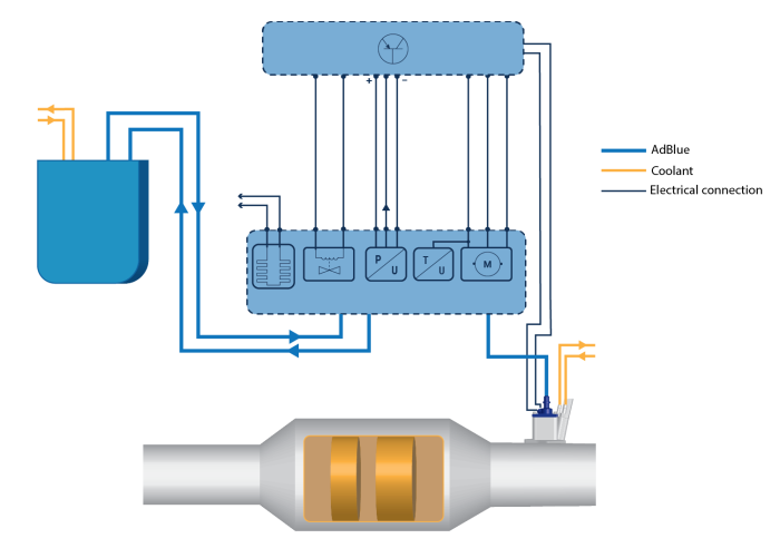
Fundamentally, there are always a set number of components for an AdBlue Aftertreatment system. These consist of:

The actuating part of the circuit is easier to explain with this hydraulic diagram:
1. Dosing supply module
2. AdBlue reservoir
3. Filter
4. One way check for the valve and throttle. Throttle is used to generate pressure by restricting the flow
5. Pressure sensor
6. 4/2 flow control valve
7. Motor-driven single direction, fixed displacement pump
8. 2/2 solenoid valve (DEF Injector)
When the ignition is switched on, the pump will prime the system once the fluid is up to temperature. The pump will draw fluid from the tank, where the pressure will begin to rise to around 9 Bar (130 psi). This pressure is created by the throttle in the return line to the reservoir, as pressure is the resistance to flow. A one-way valve prevents the fluid from entering the supply lines from the reservoir on the return side.
During operation, the injector will be commanded to open by the Aftertreatment ECU, allowing the solution to enter the exhaust system in order to begin the chemical reaction. When AdBlue is introduced to a high-temperature environment, the urea breaks down to form ammonia and Isocyanic acid. This combines with the water vapour in the process of hydrolysis and creates CO2 and NH3 (ammonia). In an environment containing a catalyst and high levels of oxygen, such as those found in lean-burn engines following combustion, the ammonia will combine with NOx present in the exhaust gas to form nitrogen, carbon dioxide and water.

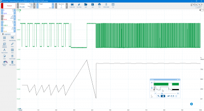
When the engine is switched off, the Aftertreatment ECU will command the 4/2 flow control valve (6.), shifting its position so that the pump is now pulling the fluid from the supply line and returning it to the reservoir. Due to the one-way valve and the closed position of the injector, a vacuum will start to build in the pipework. To prevent the collapse of the pipework, the injector is pulsed at a high frequency, in order to allow air into the pipework and control the amount of vacuum present. The pressure sensor will detect vacuum changes in the pipework, which can be useful when you are looking for blockages as shown in the case study. Please refer to this capture, taken from a known good system using an active test function from a scan tool.

It was really interesting to see that, while the injector current was flowing, we could see a drop in the AdBlue pressure. This indicates that the AdBlue was indeed being delivered into the exhaust system. As this is a known good, we can use this drop in pressure to help highlight issues with blockages in the future. If there had been problems with NOx levels despite this pressure drop, we would have to turn our attention to the spray pattern or the actual SCR catalyst.
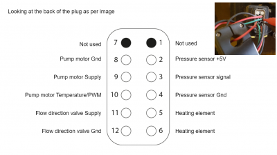
I hope you agree that this is a valid test for this particular system, especially as it's becoming increasingly common. My understanding is that the wiring is the same for all units. As such, please refer to this pin out of the plug, which will hopefully help with the connection.
There is one aspect of this system that is still a slight mystery to me and, despite trawling the internet, I've yet to find out what it means. It involves the PWM signal from the pump motor. When the pump is running it is a traditional PWM signal which we can graph with maths should we wish too. The unknown aspect is when the pump isn't running and the strange waveform that comes with it.
Aside is the known good capture where we have the oddity at the beginning, and then where the signal changes to the conventional PWM signal; this is highlighted with a math channel. This pattern looks very similar to that which Steve found on the BMW fan from a previous post.
I believe what we have here is something very similar. We know from the circuit diagram that temperature is also present on this signal, but it is not known how this measurement is interpreted. If there is some sort of data, this certainly stops when the pump is running and we have our PWM signal. We can see that the voltage levels are different between the PWM signal and the potential data which could be seen as something similar to LIN!
be sure to check out the full case study at: https://www.picoauto.com/library/case-studies/komatsu-pc210-lc-adblue-fault