PicoScope 7 Automotive
Available for Windows, Mac, and Linux, the next evolution of our diagnostic scope software is now available.
Automotive guided tests
Library of examples on how to perform tests when using PicoScope.

Training
Our collection of training videos, articles, guides and information on training courses.

Waveform library
The Waveform Library is a global database of waveforms uploaded by PicoScope users.

Case studies
Real-life case studies show how the professionals use PicoScope to diagnose vehicle faults.

A to Z of PicoScope
Detailed description of various PicoScope software and hardware features.

Videos
Training resources and demonstrations on PicoScope and the Automotive Diagnostics Kit.

Newsletter
Archive of our monthly Automotive Newsletters.

Documentation
Download manuals, brochures, posters, and training materials.

Reviews and awards
Accolades for the preferred diagnostic tool for service centers and vehicle manufacturers.

| Vehicle details: | VW Polo 1.2 3-Cyl |
| Year: | 2003 |
| Symptom: | P0106, P0172 |
| Author: | Steve Smith |
When it comes to diagnosis a cool head must be maintained when all around appears to be crumbling. Our relationship with the customer pays dividends during diagnosis where rapport is essential when things appear to go from bad to worse.
It is very easy to jump to conclusions when the evidence gathered during diagnosis points to a particular component. It is at this stage we should take stock and step away to ponder before we commit to our diagnosis.
James Dillon shares a very good comment surrounding commitment to a diagnosis:
"When replacing a component and you discover the fault is still apparent you then ask yourself, what else could it be? Why not ask yourself this same question before replacing the suspect component?"
Asking yourself this question before committing to your diagnosis could potentially lead you to the actual cause and avoid embarrassment. The case study below is one such example where taking a step back at the correct point in time saved the day.
The vehicle in question is a 1.2 3-cylinder VW Polo. The vehicle’s owner complained of power loss and intermittent cutting out at junctions (the customer had also requested a long overdue service).
A basic inspection (including a road test) confirmed no cutting out but a clear lack of performance under acceleration. A vehicle scan of the engine management revealed fault codes P0106 relating to MAP Sensor Implausible Signal and P0172, Fuel System Too Rich (Both conditions recorded as intermittent).

An inspection of live data confirmed plausible signals from the MAP Sensor, but a fuel trim value of -14% indicated considerable fuelling correction by the ECU. An emission and fuel quality test proved inconclusive and so attention was focused on the detection condition of the offending MAP Sensor fault code, P0106. The detection conditions surround the power, ground and output signals of the MAP sensor in relation to engine speed, load and throttle position.
The integrity of power and ground proved stable with the engine running and so the functionality of the sensor had to be proven.
Removal of the Map sensor highlighted typical contamination to the sensing tip as a result of crankcase breather fumes/oil mist throughout the intake manifold. A brief clean of the MAP Sensor and intake manifold port resulted in improved functionality of a component that could be attributed to the lack of power, negative fuel trim and cutting out.
A note here surrounding power, ground and signal of components such as MAP sensors:
Whilst it may be tempting to measure the signal wire only (based on the fact that if the signal is OK then power and ground must be OK), true evaluation of any component must include power, ground and signal simultaneously, unfortunately consuming three channels of your scope.
The waveform below confirms a rapid response of the MAP sensor in relation to a WOT test, accompanied with the characteristic pulsations at idle speed that can be attributed to valve open and close events.

A road test once again confirmed no cutting out but the lack of power remained. As a result further diagnosis time was now required. It is at this point customer rapport comes into play as we have used up what is fondly referred to as the Golden Hour. The Golden Hour is the one hour labour agreed with the customer to carry out a vehicle assessment and initial diagnosis resulting in a quote for the required repair, or a request for additional labour time/charge to continue the diagnosis.
Authorization via the customer allowed for an additional 1 hour labour. During this time the detection conditions surrounding fault code P0172 were pursued to include: fuel pressure, intake and exhaust integrity, 4-Gas emissions and combustion efficiency based on O2 signals. All proved inconclusive!
During the above tests it was noted that cranking time had increased before the engine would start accompanied with lumpy idle speed before stabilising. Could this be compression related as we seem to have exhausted all other possibilities?
A dynamic valve timing check was carried out utilising Camshaft and Crankshaft signals whilst drawing comparisons against an identical vehicle waveform, downloaded from the Pico Waveform Library (no fault codes had been reported of Crankshaft/Camshaft correlation!).


At last, a breakthrough in the diagnosis and something conclusive to follow. I have to say at this point, this is the second time I have used the Waveform Library during real-life diagnosis to confirm valve timing errors and both times it has proved to be successful.
Looking at the waveforms above we have an error of approximately ½ a crankshaft tooth which equates to a timing error of 3 degrees of crankshaft rotation:
Crankshaft Pick-up has 60 teeth -2 teeth for engine position reference:
360 degrees of crankshaft rotation divided by 60 teeth = 6 degrees
Each tooth equates to 6 degrees of crankshaft rotation.
Therefore ½ a crankshaft tooth (the gaps between pick-up teeth) equates to 3 degrees
With the camshaft running at ½ engine speed, 3 degrees of crankshaft rotation equates to 1.5 degrees of camshaft rotation.
Here we are looking at a small correlation error that would appear to be outside the detection of the PCM given no correlation codes have been recorded! Could this error be responsible for our Map sensor and fuel trim codes?
In order to qualify this valve timing error the rotation rulers were used to indicate 360 degrees of crankshaft rotation between each engine position reference point (missing teeth) of the crankshaft sensor signal.

With the rotation rulers in position the time rulers can be used to indicate not only time, but degrees of rotation with reference to the position of the rotation rulers (0 - 360 degrees).
Placing the time rulers at the falling edge of the 30th tooth of the Crankshaft pick-up and the rising edge of the Camshaft pick up, the time rulers indicate just over 2 ms and 3 degrees (highlighted in green) of Crankshaft/Camshaft correlation error or phase shift, confirming our calculation above.


Further analysis of the Camshaft timing error highlighted an alarming shift in the correlation during engine cranking (see above). Here we can see a shift in the relationship between the Crankshaft and Camshaft by 1.5 teeth (9 degrees of crankshaft rotation) confirming our timing chain to be skipping teeth of the timing gears.
With the confirmation of shifting valve timing, the pressure transducer was installed into each cylinder for an overview of the effects on peak compression where all were found to be normal. However, an exhaust back pressure of 1.12 bar (cranking) was clearly evident across all cylinders (see image below of all 3 cylinders overlaid using the reference waveform feature of PicoScope).

Could the exhaust back pressure be a result of shifting valve timing (1.5 teeth) or a result of an obstruction within the exhaust itself? Both have the potential to effect all cylinders equally and both could produce the symptoms described by the customer (lack of power, fuel trim correction and cutting out).
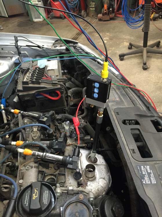
The oxygen sensor was removed and the compression hose of the WPS500X (with compression hose adaptor TA220 M18) was installed into the exhaust manifold in order to measure the back pressure during cranking.

The waveform above proves conclusively our exhaust back pressure is not a result of a blocked exhaust given the back pressure in the cylinder had climbed to 10 bar! The back pressure via the O2 sensor aperture (outside of the cylinder) returned a value of 165.3 mbar.
Things had obviously gone from bad to worse as our cylinder exhaust pressure had climbed from 1.12 bar to 10 bar! This was now getting serious and expensive as the valve timing must have slipped even further for such an increase in the cylinder pressure during the exhaust stroke. A physical valve timing inspection revealed the degree of our valve timing error!
Interesting note here was the peak compression remained high at 13.4 bar during cranking, yet our exhaust valve timing had slipped in the advanced direction by approximately 45 degrees. Had a conventional compression gauge been installed instead of the pressure transducer, the offending exhaust stroke cylinder pressure would not have been discovered leading to prolonged and possible misdiagnosis.
Why such a shift in valve timing?
Initially 9 degrees (max) at the Crankshaft to 45 degrees at the Exhaust camshaft!
I suspect a combination of:
All the above had somewhat altered the loading on the timing chain presenting irregular backlash on a worn timing chain/gears resulting in the dramatic shift in valve timing.
I think it’s worth mentioning the potential error when inspecting static valve timing using the relevant timing gear locking tools. In the case above where we have a valve timing shift of ½ a tooth, such a small deviation can be overcome when locating locking pegs and Camshaft alignment tools due to backlash in the worn timing chain/gears. A degree of movement and backlash in the worn timing chain/gear arrangement will allow for the correct alignment of timing gear locking tools suggesting the valve timing to be correct!
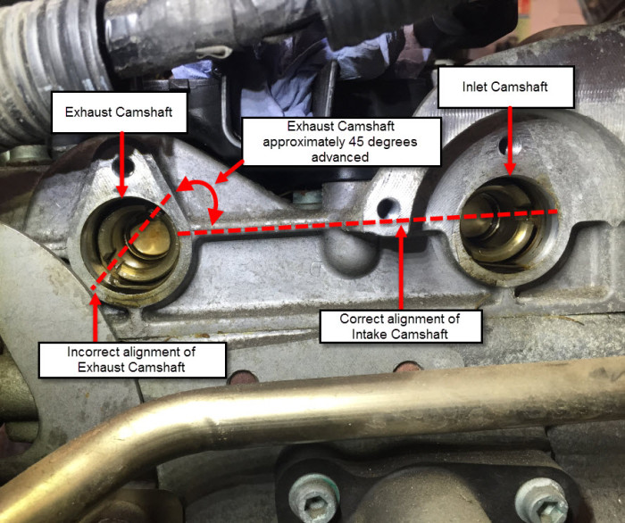
Equally when carrying out a dynamic valve timing check using Crankshaft and Camshaft signals, whilst we can measure the slightest deviation in Crankshaft and Camshaft correlation we must remain aware of the location of the Camshaft Sensors when dealing with multiple Camshaft engines.
In the example above the camshaft sensor detects the position of the Inlet Camshaft only and assumes the position the Exhaust Camshaft to be correct. Assumptions must never accompany diagnosis.
True evaluation of valve timing is therefore a threefold process using a combination of static and dynamic checks accompanied with in-cylinder pressure measurements to confirm individual cylinder valve timing.
So why do we need to measure the valve timing of individual cylinders when we have verified Crankshaft and Camshaft positions, zero backlash and the correct relationship between all timing gears and shafts?
What about valve clearances? (See our Subaru case study for more info: https://www.picoauto.com/library/case-studies/2012-subaru-flat-4-cylinder-misfire-p0302)
How about: worn camshaft lobes, poor alignment or installation of Camshafts, broken/insecure rockers, compressed hydraulic lifters or Camshaft lobes that have spun independent of the Camshaft? All these conditions will adjust the independent valve timing of each cylinder.
Another consideration; engines that utilise variable valve timing! Here we need to disable the relevant valve actuator in order to restore the engine to a default valve timing position (often the maximum retarded safe valve timing position). With the valve timing fixed, individual cylinder valve timing can be measured.
With all the above in mind, could we also have damage to an inlet or exhaust valve as a result of “collision” between the valve gear and piston? Our in-cylinder pressure waveform would suggest not given we can generate over 13 bar on the compression stoke and 10 bar once again during the exhaust stroke. (Deformed valves would result in zero compression values)
Permission was given by the customer to inspect the timing gear/ chain assembly for wear and provide an assessment of the potential costs involved for repair.


Like any valve timing error we all know the potential for valve damage and so it only seemed logical to momentarily run the engine and confirm the integrity of the valve gear before committing to a timing chain repair only! In order to run the engine, the sump pan was re-installed and primed with oil to maintain oil pressure, whilst timing chain tension was managed using a pry bar to ensure zero backlash.

The obtained results were devastating to say the least as the engine would not run, accompanied with excessive cranking speed and popping via the intake and exhaust system that certainly spelt the end for this engine; or did it?
The compression test results below suggested compression loss and individual in-cylinder valve timing errors! However, the expansion pocket formed at the base of the expansion stroke confirmed the Intake and Exhaust valves to be seating correctly, therefore not deformed!

I mentioned at the start of this case study “It is very easy to jump to conclusions when the evidence gathered during diagnosis points to a particular component. It is at this stage we should take stock and step away to ponder before we commit to our diagnosis” .
I also mentioned how "taking a step back at the correct point in time saved the day", well here it is.
In the heat of diagnosis and the results gathered to date, I was most certainly going to recommend the cylinder head be removed for further examination until my colleague (Kevin at Ives Garage) suggested the following:
Could these new symptoms (excessive cranking speed, intake and exhaust popping) be attributed to hydraulic lifter/ valve clearance characteristics as a result of Camshaft rotation by hand with insufficient oil pressure to replenish the lifters? If so, how could we prove this scenario?
How about temporarily installing the timing chain whilst cranking the engine (spark plugs removed) and monitoring the cylinder pressure during the replenishment of the hydraulic lifters? It was most certainly worth a shot!
Take a look at the waveform below where we can see the peak compression build from 2.7 bar to 7.6 bar (cyl 2) after 3 minutes of cranking. This can only be attributed to the progressive correction of individual valve timing and valve seating, as a direct result of the replenishment of the hydraulic valve lifters. It would be very difficult to visualize this event whilst plotting the build in compression against time using a conventional compression gauge. Here we now have the evidence required to support a timing chain/timing gear replacement only (the cylinder head can remain intact).

Permission was given by the customer to replace the timing chain set, whereby upon reassembly (and a little cranking) the vehicle ran as normal with no fault codes and restored power.


The waveforms above highlight our in-cylinder pressure and in-cylinder-valve timing after fix at idle speed and the Crankshaft and Camshaft correlation (after fix during cranking).
To conclude
Food for thought
The evolution of the internal combustion engine and the need to reduce cost of ownership has seen a rise in chain driven engines. There is most certainly a pattern forming with such engines where timing chains appear to stretch over time, accompanied with questionable tensioner efficiency presenting Crankshaft/Camshaft correlation issues, that were not so frequent with belt driven engines.
Whether this is a result of the components used during manufacture, long-life service intervals, inferior engine oils or just an enthusiastic driving style, I am not sure. With this case study in mind, I think there is real value in dynamic valve timing checks during routine maintenance in order to obtain a timing gear signature for the engine under test.
These captured waveforms (timing chain signatures) can be used to monitor timing chain wear over time at each scheduled service protecting both the customer and workshop whilst presenting a potential repair opportunity.
Could we possibly a see a time where we revert to belt driven engines with recommended replacement intervals?
A big thank you to Pico Phil and Kevin of Ives Garage for their valued input during this challenging diagnostic journey.
Todeschini Cristian
November 01 2015
Thank you for your work.
My experience regarding different detections of the dynamic phase has taught that it is difficult to have perfect references with sample signals, especially in the starting phase, where the belts or chains have greater flutter.
As reported in the text have to assess the value of the deviation, and the technology applied to the motor, for example, if the gears have the block key, the number of teeth of the gears. In case of phase shifter on the camshafts is sometimes not enough to disconnect the control solenoid valve, some VVT do not have return springs and rely on mechanical-hydraulics blocks who do not always work, it would be desirable to leave the solenoid valve connected to and sample the signal command and compare it, together with the dynamic phase, with the reference signals.
The detection of an out of phase with sensor WPS during the start-up phase hardly detects a displacement of a single tooth of the camshaft, while for higher values, as in the case studied, is very useful.
Greetings
jon amos
October 31 2015
just a thought?, would a vacuum gauge not of told you in the beginning that something was up with valve timing, and back pressure
carl keenan
October 31 2015
Great report. Very complex & easily misleading symptoms. Testimony to your persistence in getting to the bottom of the fault. I would be interested to know how long it took to get to the bottom of the fault? I have been considering buying the WPS500X pressure transducer for some time now. This is just another very good reason to do so. Thanks for sharing this job.
P.Dubnyck
October 31 2015
Dear Sirs,
Thanks for your most interesting tale of diagnosis. I am impressed with the amount of technology used to come to a fairly simple conclusion.
As someone who has driven an overhead chain driven cam engine for over 30 years (Alfa Romeo Guila Super), I have only replaced the cam chain once in 180000 miles and since it did not have hydraulic lifters there was not an issue there. Also the adjuster was fixed, not hydraulic so once it was adjusted it stayed that way.
My current vehicle ( Nissan patrol) also has a chain driven cam.
My point is that I would NOT want a vehicle with belt driven cams. I have known such to generate huge repair costs if owners are not aware that they need regular(expensive) replacement.
Once again thanks for the valuable information,. I am now going out to check my valve timing but it should be ok since its only single cam.
Rgds.


