PicoScope 7 Automotive
Available for Windows, Mac, and Linux, the next evolution of our diagnostic scope software is now available.
Automotive guided tests
Library of examples on how to perform tests when using PicoScope.

Training
Our collection of training videos, articles, guides and information on training courses.

Waveform library
The Waveform Library is a global database of waveforms uploaded by PicoScope users.

Case studies
Real-life case studies show how the professionals use PicoScope to diagnose vehicle faults.

A to Z of PicoScope
Detailed description of various PicoScope software and hardware features.

Videos
Training resources and demonstrations on PicoScope and the Automotive Diagnostics Kit.

Newsletter
Archive of our monthly Automotive Newsletters.

Documentation
Download manuals, brochures, posters, and training materials.

Reviews and awards
Accolades for the preferred diagnostic tool for service centers and vehicle manufacturers.

| Vehicle details: | V8 |
| Symptom: | MIL on but no symptoms |
| Author: | Nick Hibberd | Hibtech Auto-Electrical Diagnostics |
The vehicle arrived with the engine MIL on but with no noticeable running problem. Checking the system with a scan tool, I found these diagnostic messages:
Because the trouble codes relate to different aspects of the engine management, it was unlikely that either had any effect on the other. However, the faults were logged by the ECM for a reason and either of them could equally have caused the MIL to flag. It’s also unlikely that both events occurred at the exact same moment, so which one was the cause of the MIL flagging this time?
Look at this logically. Most stored trouble codes sit in the Engine Control Module’s memory until viewed and erased by a scan tool but, unfortunately, this opens the way for many stored faults to be present when often only one relates to the customer’s present complaint. The problem is aggravated if the last fault wasn’t erased from the ECM’s memory after it was rectified, so good technicians never leave old codes behind like this. To make sure, I recorded and erased the codes in an in attempt to see which one was the offending problem, the plan being to drive the vehicle and subject it to various driving conditions whilst monitoring for any trouble codes. As it happened, merely keying on caused a stored fault:
Knock sensor Cyl 1-2-7-8
The engine is a V8 with two knock sensors installed, one monitoring cylinders 1-2-7-8 and the other cylinders 3-4-5-6. The sensors themselves are mounted at the bottom of the V and between the cylinder heads.
The sensor’s detecting element is a piezoelectric crystal which, when at rest, has no voltage across it. However, when subjected to mechanical pressure at the knock frequency, which is typically around 15 kHz, the crystal’s electrical structure becomes distorted, producing a voltage output. The emitted electrical signal is directly proportional the severity of the pressure or knock. This signal is interpreted by the ECM’s knock control strategy which alters ignition timing, and sometimes fuel delivery, in stages until the knock disappears. Backing off ignition timing for that cylinder is standard practice, while any other conditional tweaks performed by the ECM depend on the system.
There are various types of connection between the knock sensor and the engine management unit. Some early management systems only had a single cable running between them and the knock sensor; some knock sensors have two cables, where the second one acts as both a shield and a signal ground reference; some bias the signal line above chassis ground and the knock signal modulates the dc voltage; and some designs have a separate control unit (A/D converter) entirely dedicated to interpreting the knock signal before it reaches the ECM.
Once supplied with a knock sensor signal, the ECM’s diagnostic procedure can vary. The knock control strategy itself used by most ECMs predicts when a combustion knock will occur, so the ECM only listens to the knock sensor signal just before and after combustion. This reduces the chance of the sensor picking up stray signals that the ECM may incorrectly interpret as a knock.
What stirred my curiosity was the trouble code itself, which showed the ECM’s ability to detect a problem within the knock circuit with just the ignition on, when no engine knock was present nor expected.
The system configuration was investigated further to form an understanding of this fault detection strategy and the sensor’s general operating characteristics.
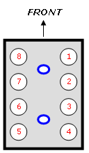
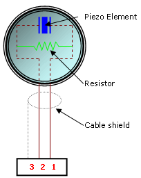
Each knock sensor had three cables connected, two running straight to the ECM and one providing a ground path and signal shield. The signal recorded at pin 1 never altered much above ground potential but, because this cable came from the ECM, it was deemed to be more of a ground reference to the sensor rather than a direct chassis ground. Pin 2 was the line out carrying knock information from the sensor to the ECM. It was also this cable that revealed most of the diagnostics performed by the ECM. Pin 3 was a direct connection to chassis ground.
The sensor incorporates a shunt resistor across pins 1 and 2 that measured about 560 kΩ in a known good example. The polarity of the test leads is not important for this measurement.
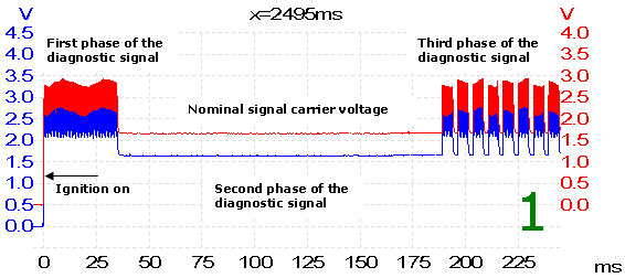
Capture 1 was taken during one key-on cycle. Each channel is monitoring one knock sensor’s signal line. For ease of viewing, the Red channel has been slightly offset to give a clearer comparison. The trace follows each sensor’s signal line from the moment ignition is switched on. Even though we can’t clearly see the signature itself here, we can definitely spot a pattern and a near perfect correlation between the two sensors.
The diagnosis that the ECM performs seems to be in three phases that make up the whole recorded trace. Immediately after ignition is switched on, the ECM produces a high-frequency sine oscillation, then a nominal carrier voltage hangs on the signal line, and finally there is a combination of the first two phases switching between each other rapidly. Incidentally, this third phase would remain present whenever the ignition was on; if the engine started, only the carrier voltage would remain. The following captures carry on from 1 and illustrate the same recorded signal, except now focusing on the different phases of the whole trace.
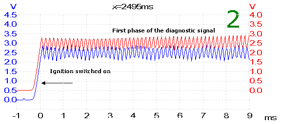
Capture 2 shows the first stage in more detail as ignition is switched on. It lasts for about 35 ms and the oscillations seen have a frequency of about 5.6 kHz.
| Hertz (Hz) | = | cycles per second |
| Approximate distance between each peak | = | 177 µs (0.000177 seconds) |
| 1 second / 0.000177 second | = | 5649 cycles per second |
| = | 5.6 kHz |
Although the two signals look similar, they can be seen to drift slightly apart from one another in time, which offers a clue that two separate diagnostics are used. This makes sense, because we know that the ECM can determine which of the two knock sensor circuits is faulty.

The nominal carrier voltage that the ECM hangs on the line seems consistent and interference-free throughout. Both signal lines here read about 1.6 V.

Capture 4 shows more clearly a combination of the signals captured in 2 and 3. This repeated signal has about a 4.8 ms duration incorporating the same 5.6 kHz oscillation. The main factor here is the oscillations themselves, as these seem to be fundamental to the ECM’s diagnosis of the sensor and circuit. An interesting characteristic of any piezoelectric element is its ability to act as both a sensor and an actuator. In this application, the element's purpose is to react to a certain mechanical vibration frequency (combustion knock) then produce a voltage proportional to those vibrations, but it can also work the other way. If the element is supplied with an oscillating voltage, it produces a very small mechanical movement in the form of waves at the supplied frequency. It’s likely that this 5.6 kHz oscillation is used to excite the piezoelectric element.
Anonymous
February 18 2015
FINALLY! somebody explains how the thing works. Now I know why im having problems. hate throwing parts at a problem without understanding whats going on. Thank you
steve hiatt
August 23 2013
i had a P0235 DTC “knock sensor” so changed my KS but got barely 0.005 volts supply - does that sound like an ECU fault?
ray
January 05 2013
is there not a simpler methgode for car repair shops time is limited
otherwise the article is great
Klapa
September 20 2011
Very well thought out and informative article!
I am an electronics engineer by trade interested in developing auxiliary ECU modules for sports cars (this is my hobby). This article helped immensely - especially with your most methodical test technique.
I appreciate the effort you made to document your efforts and share that.
Ron Ingram
May 19 2010
Very informative article. It really helped repairing my son’s LEXUS ES300. His problem turned out to be an open line on sensor #2. In this case we bridged the ECM inputs for sensor #1 and #2, and ran only sensor #1 to the brige. This tricked the computer to allow the car to operate in a normal mode.
John
December 02 2009
That was a great description of what you did and why.
I’m building my own knock sensor for a 1972 car, so now I now what to expext from the sensor. The rest of the circuit is relitivley simple. It only has to light an LED and latch it.
Roger
September 19 2008
Having established that the faulty sensor had a resistance reading of 2.5 Mohm when it should have been 560 kohm why did you not measure the resistance of the resistor during the dismantling of the sensor? The Piezo part of the sensor is in theory an infinite resistence at dc and that was confirmed by the measurements. You could have replaced the resistor and put the sensor back into the vehicle and it should have worked properly again. Just an observation for the future! Note that this could have been achieved by putting an external 560 k resistor across the plug pins.
DIY'er
September 15 2008
Great explanation, gives real insight to the techniques possible in the circuit designs.


