PicoScope 7 Automotive
Available for Windows, Mac, and Linux, the next evolution of our diagnostic scope software is now available.
| Vehicle details: | Honda CR-V |
| Engine code: | N22A2 |
| Year: | 2007 |
| Symptom: | Engine surging, Poor acceleration |
| Author: | Pico | Steve Smith |
|
Manufacturer: |
Honda CR-V 2.2CDTi 2007 RE 6 N22A2 Manual 86750 Performance FRP accessory kit |
During hard acceleration, the vehicle violently surges back and forth.
When the accelerator pedal is released, the vehicle resumes normal driving performance.
The symptom is evident regardless of engine temperature, and is present whenever the driver attempts hard acceleration (the symptom is permanent).
The symptom has been evident since purchase (recent auction sale).
As indicated by the customer, the vehicle surges abruptly under Wide-Open Throttle (WOT) and it appears worse during hill climbing.
No warning lights were present and the vehicle could be driven normally with no drivability issues when avoiding hard acceleration
No unusual levels of exhaust smoke visible under hard acceleration.
The customer interview points out lack of historical information, as the vehicle had just been purchased at auction.
The customer complaint was verified and the vehicle’s ID and specification were confirmed.
The basic inspection confirmed connections, hoses, harness routing, and fuel quality as correct. However, it also revealed that an accessory had been installed in series with the fuel rail pressure (FRP) sensor. Even though it was tempting to simply remove this accessory and road test the vehicle, it was necessary, in order to qualify and prove a potential repair, to capture data with the vehicle in the error state.
A vehicle scan confirmed no fault codes, and an overview of engine data parameters confirmed that the engine was running as normal during both idle speed and a free-rev test at 3000 rpm.
Available data confirmed no known issues of this nature.
The PCM software level is confirmed as correct for the specification of vehicle (no relevant updates).
Description and operation data from Denso was referenced for in-depth knowledge of component functions
Possible causes based on symptom and evaluations made above:
The action plan is based on initial evaluation, experience, and accessibility, so the accelerator pedal position (APP) sensor and fuel pressure control circuit were chosen for evaluations (especially given the accessory installed to the FRP sensor).
Due to the nature of the symptom, the vehicle had to be driven under WOT to reveal the errors in any of the engine management inputs/outputs.
Based on the action plan the scan tool was then connected to monitor all engine parameters, and PicoScope was connected to monitor specific inputs in real-time:
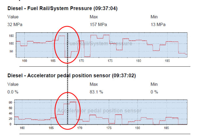
Scan data initially indicates a discrepancy with the common rail fuel pressure in relation to the position of the accelerator pedal.
The illustration shows the fuel pressure falling to zero MPa, even though the driver demand (position of accelerator pedal) is high.

Although this data is an indication of a possible error, the resolution from the scan tool is extremely poor.
The scan tool equips us with the ability to collectively monitor multiple inputs with reduced update speed, while the scope allows us to look closer at the sensors in real-time.
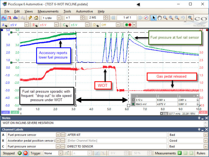
The following results, however, are conclusive as illustrated in the PicoScope trace below.
Ch. A (Blue) indicates the fuel pressure signal measured at the output of the FRP accessory kit, while Ch. C (Green) confirms the actual rail pressure. Ch. B (Red) indicates the gas pedal position/driver demand.

From the waveform, we can see how the FRP accessory kit is designed to convince the PCM that the fuel pressure is lower than expected. This results in an increased pressure output from the common rail diesel pump and, theoretically, an increase in performance.
During initial acceleration both fuel pressure values rise as expected, with the lower fuel pressure signal from the FRP accessory kit consistently tracking the actual fuel pressure signal. As the fuel pressure approaches maximum, both signals drop rapidly before they repeatedly attempt to recover again, simulating idle pressure values of 0.7 V and maximum pressure values of 4.6 V in approximately 200 ms under WOT (driveability was dreadful under these conditions). Once the demand was removed from the fuel system (gas pedal released) fuel pressure values recovered and then decayed as normal.
N/A
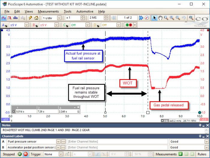
After confirming that the power and ground supplies to the fuel rail pressure sensor remained stable throughout WOT driving, the most obvious step was to remove the the FRP accessory kit and road test the vehicle under conditions with WOT and full load (to qualify and confirm any repairs).

The waveform above confirms fuel rail pressure remains stable throughout WOT.

As the performance kit was discovered early, during the basic diagnosis process (check for accessory installations), it would have been very tempting to simply remove the device, road test, and assume everything was in working order. However, assumptions and diagnosis do not go hand in hand.
Following the procedure above, we have not only confirmed that the FRP accessory kit was the offending component, but also confirmed that the vehicle performed correctly after the fix, showing no signs of the initial complaint and no consequencial damage.
Jonny
March 16 2016
Great Job. Just wondering, do you think the pulsing effect was caused by a fault within the accessory, or a safety feature within the vehicles control system? Perhaps the rail pressure release valve was opening? Or the pressure regulator was reaching an upper limit value?
Dave Wagner
March 10 2016
Great job putting that case study together, I like how you compared the manipulated readings to actual fuel pressure. That would work well for fuel trim issues as well.
Ahti
March 01 2016
Nice case study but i would have liked to see what happened to fuel pressure regulator solenoid(s).
Thes boxes create many problems and I have removed many of these because fuel pressure problems.