PicoScope 7 Automotive
Available for Windows, Mac, and Linux, the next evolution of our diagnostic scope software is now available.
Automotive guided tests
Library of examples on how to perform tests when using PicoScope.

Training
Our collection of training videos, articles, guides and information on training courses.

Waveform library
The Waveform Library is a global database of waveforms uploaded by PicoScope users.

Case studies
Real-life case studies show how the professionals use PicoScope to diagnose vehicle faults.

A to Z of PicoScope
Detailed description of various PicoScope software and hardware features.

Videos
Training resources and demonstrations on PicoScope and the Automotive Diagnostics Kit.

Newsletter
Archive of our monthly Automotive Newsletters.

Documentation
Download manuals, brochures, posters, and training materials.

Reviews and awards
Accolades for the preferred diagnostic tool for service centers and vehicle manufacturers.

| Vehicle details: | New Flyer 60ft Articulated Bus |
| Year: | 2001 |
| Symptom: | Black smoke, Misfire |
| Author: | Michael Eilbracht Diagnostician at MJE Diagnostics |
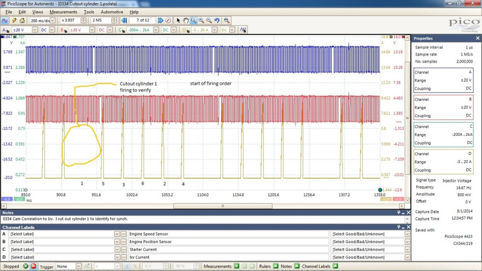
This bus I worked on took a little time to figure out but was very interesting in the end result of what the fix was. The initial complaint on this bus was excessive black smoke on acceleration and the occasional random misfire. So the first thing I did was I checked for codes and no codes. From past experience, I have seen injectors leak which will cause this issue so I decided to do a cylinder cut-out test with Cummins Insite factory tool. So to elaborate a little further on how the cylinder cut-out test works on this engine, the ECM looks at engine position and engine speed with the two sensors mounted on the back of timing cover. When you command a certain cylinder off it knows when to disable the Injection control valve on the injection pump.
The Injection Control Valve (ICV) is responsible for metering the fuel at the exact moment the distributor lines up with the adjacent slot going to that particular cylinder. This injection pump on this bus is a distributor type pump with an accumulator on top that has two pumping chambers which are electronically controlled by solenoids. The pressure is built inside the accumulator housing and then goes to the ICV for metering of the fuel, which meters it at the proper firing order of the engine. The firing order is 153624 on this inline configuration.
Here is an example of showing the number one cylinder being cut-out and me looking at it on my PicoScope. I did the cut-out test and noticed that the RPM drops on all of the cylinders were not even. Sometimes they were OK, sometimes they were not. After discussing this with my foreman we decided to put six new injectors in because of the nature of the problem.
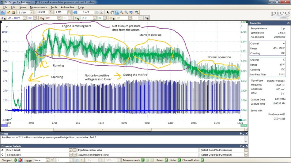
After doing this, lunch time came and my curiosity made me hook up my PicoScope to the accumulator pressure sensor which is threaded into the back of the accumulator housing on this pump. I was hoping to see injectors dropping too much pressure. However in this case, I was not seeing what I hoped to see. On the second pic I noticed that as the engine started to run the accumulator pressure on Channel C was very unsteady at the beginning of engine run and then levelled out and lowered. The lowest point of the green trace is when the engine started to idle smooth again.
I then zoomed in with the Pico at the high peaks and valleys of the accumulator pressure sensor and noticed that four of the injectors were barely dropping any pressure. Then at the end of capture you see somewhat even pressure drops. To be honest, after looking at the scope capture, I was a little sceptical now with the injectors being the issue. So we had the injectors done and ran the bus.

The next day the bus came back with the same complaint. At this point, I hooked up Insite again and looked to see if any data looked amiss. Everything looked good. Boost was good, I had 38 to 40 inches of mercury, my air filter checked out ok, and the data PID for injection control valve circuit status said normal. So after this I decided to hook up my PicoScope to the ICV because it is in charge of the proper fuel metering to the cylinders. I start up the Bus and I notice that the ICV current is intermittently dropping out. Awesome! I now have direction on what to do next. In the next file I am zoomed in to look at ICV current, voltage, and pressure, which is the red trace and the ICV voltage is the blue trace. This pic is showing the ICV is staying on longer than it should be and it does not have a clean cut off. Also the pressure is erratic too and is choppy showing that the ICV is sticking. After seeing this, it was the end of the day and I told the night foreman to double check the power and ground wires to the ICV and if it checked out ok, to replace the ICV and the transient suppressor.


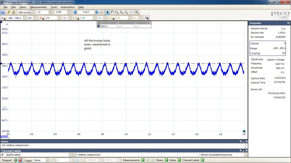
I came in the next day and my foreman told me the problem was still there. So what did I miss? I decided to recheck everything, pump timing, fuel leaks, electrical connectors at sensors, fuel return line blockage, and everything was ok. So after this, my foreman wanted me to do a relative compression test with my scope. The relative compression checked out fine.
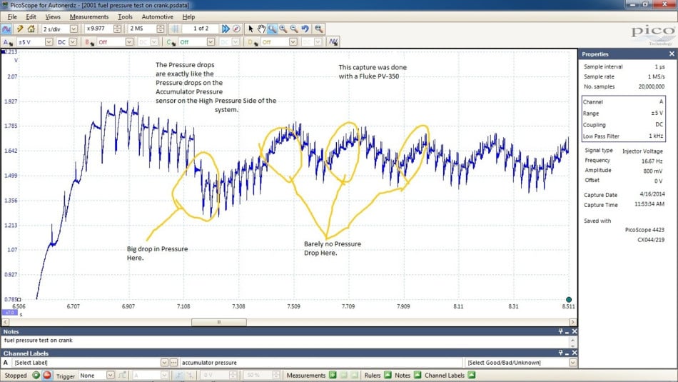
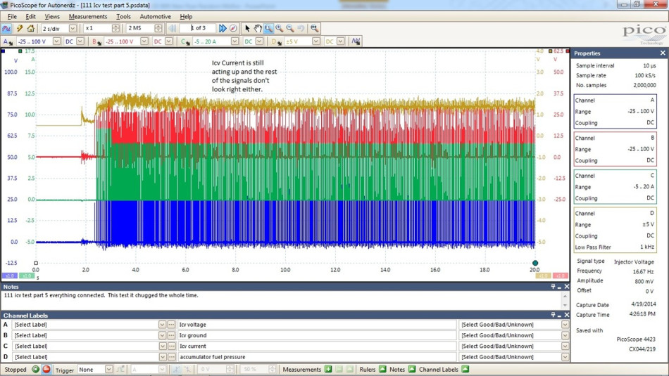
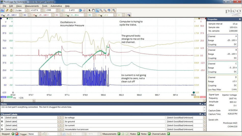
After this test I wanted to see if the low side gear pump pressure mimicked the high side on a crank and start. I checked the low side gear pump pressure with a Fluke PV 350. I show in these two pictures how unsteady the pressure is just like the high side is. I then went back to checking the ICV. I hooked up to voltage, ground, current, and pressure. The first picture shows me taking a long screen so I can see trends in the signals. This is why I like the PicoScope so much is because of this feature. I zoom in on the capture and notice that the accumulator pressure has huge up and down dips when the ICV is trying to work. The ICV current then drifts at 2.5 A for a while and the accumulator pressure drops accounts for this. The red trace which is ground does not look right to me. At first I thought it should be 3 to 400 mV at most. However the ground voltage is creeping up in conjunction with the ICV current. My pressure drops are erratic as well. My feed voltage is good though.

The reason why we have black smoke on acceleration is because of this valve not closing properly and therefore putting more fuel into the cylinders. It was the end of the day and I went home and thought about it overnight. What could be causing this weird operation of the ICV? At that moment the light bulb went off in my head! When the night shift replaced the ICV valve did they replace the transient suppressor? If they didn't, this would explain this weird operation! The transient suppressor is basically a capacitor which absorbs the electromagnetic field dump of the ICV so the ICV can close properly. If it isn't working you will see this type of operation. Since there is nowhere for the electromagnetic field to be absorbed quickly the field rings or resonates till all the energy is gone.
So I came in the next day and we checked the suppressor and found that the night shift had not replaced it! So I proceeded to put a new one on and noticed that while I took it off it was not plugged in! Bingo! I replaced the suppressor and it had no more black smoke! Problem fixed! My foreman took it out on a test drive and had no more issues.

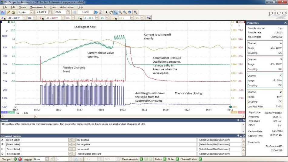
Here in the last pic shows what a good ICV circuit and pressure drops should look like. You can also see that on the ground side it shows the magnetic field spike and the suppressor is capping it off around 50 V. You then see a hump at the end showing that the ICV is closing. This was a very cool problem in my opinion. The scan tool told me nothing helpful whatsoever. If I did not have a scope I would not have been able to find this issue. My foreman would have told me to replace the entire pump which is over two thousand dollars. I saved the company I work for quite a bit of money. I was initially right in my diagnosis, it's just the second shift forgot to replace the transient suppressor.
Michael John Eilbracht
June 04 2020
The Icv Valve Stator had pitting in it and also the valve was sticking.
Neil
December 30 2018
Great Diag!
Andres
November 16 2018
So in this case the client was charged for 6 new injectors, the ICV and the transient suppressor, but all the bus needed was to properly connect the transient suppressor?


