PicoScope 7 Automotive
Available for Windows, Mac, and Linux, the next evolution of our diagnostic scope software is now available.
Automotive guided tests
Library of examples on how to perform tests when using PicoScope.

Training
Our collection of training videos, articles, guides and information on training courses.

Waveform library
The Waveform Library is a global database of waveforms uploaded by PicoScope users.

Case studies
Real-life case studies show how the professionals use PicoScope to diagnose vehicle faults.

A to Z of PicoScope
Detailed description of various PicoScope software and hardware features.

Videos
Training resources and demonstrations on PicoScope and the Automotive Diagnostics Kit.

Newsletter
Archive of our monthly Automotive Newsletters.

Documentation
Download manuals, brochures, posters, and training materials.

Reviews and awards
Accolades for the preferred diagnostic tool for service centers and vehicle manufacturers.

| Vehicle details: | Unspecified |
| Symptom: | Poor interior temperature control |
| Author: | Nick Hibberd | Hibtech Auto-Electrical Diagnostics |
The customer complained that the interior temperature would occasionally hang at one setting. He couldn’t say at which temperature this happened, just that sometimes it stopped working. I decided to investigate.
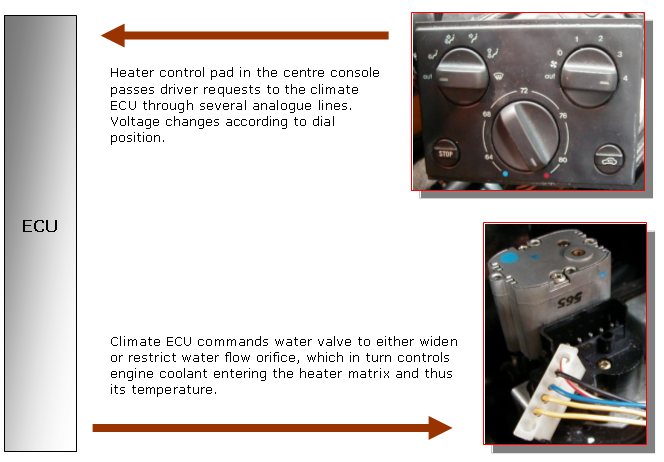
Where to start? I always preach “start at the beginning”, but in this case the beginning for me is actually the end of the circuit: the water valve, which dictates matrix coolant flow and thus the interior temperature.
Call me old-fashioned but, looking at the setup, there aren’t too many ways this can work. There are 5 cables and I’m guessing that two are for motor command (both cables carrying switched-polarity feeds) and the other three provide a valve position feedback (potentiometer supply in, ground in, and variable voltage out).
The customer said that the fault happened “occasionally”, and at this moment the valve seemed to be working fine, so this was a great opportunity to collect some real-time readings. With any new circuit under test or investigation, I don’t take any reading for granted. I have to see a unit working comfortably in its own environment first, and make sure the controlling ECU is happy with things, before I finally log it as a known good example.
I back-probed the valve’s electrical connector and soon discovered that my operational theory was correct.

Next the scope hook-up. I wanted to get an all-round performance picture from the valve, and the best way I’ve found from similar configurations to this is to monitor motor current draw and position feedback signal. Why?
Motor current draw, because this measurement includes verification of the cabling to and from the motor, all relevant connections along the way, and motor integrity; with the added bonus of analysing motor effort, which is an often-forgotten diagnostic aid. All this through one hook-up and using only one scope channel. Signal measurement checks in voltage form are still helpful, but you only get a small part of the big picture.
Position feedback signal, because this on its own offers excellent performance information for the entire potentiometer circuit (providing we are dealing with contact slider variety Ᾱ which we are). It’s useful for the obvious monitoring position of the valve and slider contact integrity, but can also provide information about potentiometer circuit failure and likely causes.
With the scope connected, I carried out a couple of full sweep tests from the heater control panel with seemingly excellent response from the valve. See capture 1.

I continued testing the valve for some time with no real sign of a fault. I put the valve in different positions, slow progressive rotations, fast alternating directions, switching ignition off then powering back up, but it soon became tedious. The question has to be asked: how long do you test an intermittent fault? I like to give the component or circuit ample chance to fail.
You just know that as soon as the customer returns to his car, the fault will occur, and he then may question your willingness to investigate the problem: “Have you tried to get it to fault?” Sometimes as an Auto Electrician I feel there is no winning, only degrees of losing. The test duration in this case was about 30 minutes, a fair length of time.
Anyway, I just about reached the end and was about to pack up when I saw something right at the very edge of one particular capture. By this time, I had shortened the screen capture time to get a more detailed look at the motor commutation, but I was sat in the passenger compartment and I wasn’t quick enough to reach the PC and hit the STOP button, so there are no saved captures — sorry. But I know I did see something.
I opened the time base up again and crossed my fingers for the fault to recur. A few full sweep operations later and ...GOTCHA!


First and foremost is the obvious current reading going out of capture range (above 1 amp), which actually offers the biggest clue to the fault.
At the beginning of the investigation I played around with different scope vertical divisions to get a suitable display for the motor current draw, which if you look back at capture 1 turned out to be around 200 mA during lock-draw. I set the scope vertically to ±1 amp, hoping to get a safe window of operation.
The current bursts are certainly sudden and have a periodic feel about them, suggesting that the motor is becoming loaded. Is the valve hitting something along the way and jamming, perhaps? This would be the most obvious answer, but unfortunately, no. We can rule out any problem with the mechanical aspect of the valve because this, as we have seen in capture 1, would at worst only simulate the motor lock-draw current of 200 mA. It’s worth mentioning that this 200 mA during normal operation is entirely due to circuit resistance (obviously including the motor at near 50 Ω). At this point in the operation the ECU has no influence on limiting current flow. And, as we can see, should a fault develop then the ECU current limiter will take over, but unfortunately we can’t see from the capture what this limit is.
Maybe the fault is nothing to do with the motor or the valve. An ECU or cabling fault, perhaps?
Again no, not because it’s electrically impossible, but because of the test point location used. I’ll explain. Referring back to any of the captures used in this investigation, notice that we can’t see the motor supply polarity because until now I’ve used only the current probe for diagnosis. I now need to include the supply polarity to be confident of any conclusion. Firstly, a cable open circuit (high resistance) would result in no (or very little) current flow; just the opposite condition to what we are dealing with here, so this can be ruled out. Perhaps, more specifically, a cable short then? Well, this is typically the cause of most excessive current draws, so let’s have a look at the possible supply polarity combinations. I have to admit I didn’t pay much care to polarity at the time of test; I set the scope, zeroed the current probe and clamped it around one of my motor cables. I was after a general outlook on circuit performance, and that is what I got.

From the above illustration we really only have one possible contender. Now let’s consider the other alternative supply polarity and see the difference this makes to our findings.
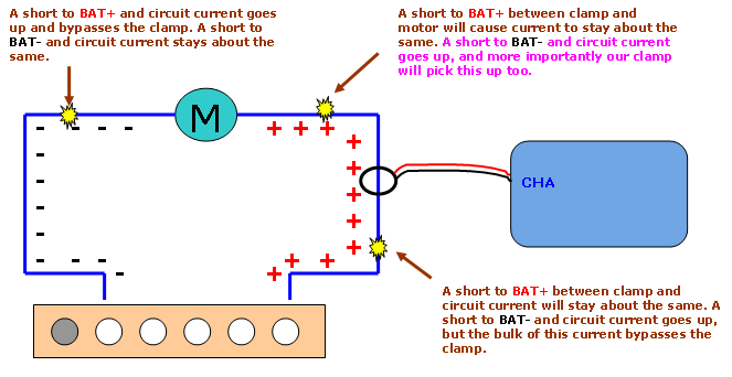
I think I’ve covered all the short-circuit possibilities! If we look at all the contenders, we can see a pattern emerging, in that our possible short would have to occur between the load (motor) and the chosen clamp measuring point. I can comfortably rule out any of these by stating that my measuring point was just a short way down from the motor and with the cabling in clear sight; so a cable problem was out of the question. Nevertheless, each one had to be considered to be sure of my final conclusion - an electrical short inside the motor.
The capture held other clues about the fault, too.

The rise in position signal at the same time as our current bursts is indication of power supply sharing within the ECU; not much of a diagnostic clue but interesting all the same. In particular, it looks as if here the ground connection was shared by both circuits.
Each sudden current burst indicates our fault. The sequence of events continues with the ECU cancelling current briefly before reapplying current into the circuit to try again. The sweeping curves at the bottom as current is reapplied tell a story too. The motor almost instantly runs into trouble and we see a characteristic curve form. This curve then levels out at around 200 mA, indicating that the motor has hit a tight spot, and soon after this we see the current burst. And notice how the duration between current bursts increases until finally the fault is overcome.

As to what was wrong inside the motor assembly, well I’m open to offers on this one. It would be all too easy to assign a shorted armature winding but I just don’t believe that’s it. My own thoughts are leaning towards a brush location problem, or perhaps even armature drift, but each theory I came up with had a flaw of some sort. This is clearly a dead short and there aren’t too many causes of this. Unusually high or low resistances sure, but a very intermittent dead short?
I’ll leave this one open…
A new motor/valve assembly was installed and things have been well since.
Brandon H Steckler
December 10 2010
Im truly intrigued by all of the great diagnostic-techniques you use…whats more impressive is that you share this info with all of us in great detail…THANK YOU! I’ve learned a lot so far…why not disassemble the motor and inspect it???
GJ
October 14 2009
Is it possible there is a problem in the motor to cause it to “wobble” around one position? It could be a pure mecanical fault then. The current is not nessecairy a short circuit, it could be induced by the motor itself, generated by this “wobbling”.
GJ_
October 14 2009
about my comment:
sorry for my poor English.
Gerrit Jan
.(JavaScript must be enabled to view this email address)


