PicoScope 7 Automotive
Available for Windows, Mac, and Linux, the next evolution of our diagnostic scope software is now available.
Automotive guided tests
Library of examples on how to perform tests when using PicoScope.

Training
Our collection of training videos, articles, guides and information on training courses.

Waveform library
The Waveform Library is a global database of waveforms uploaded by PicoScope users.

Case studies
Real-life case studies show how the professionals use PicoScope to diagnose vehicle faults.

A to Z of PicoScope
Detailed description of various PicoScope software and hardware features.

Videos
Training resources and demonstrations on PicoScope and the Automotive Diagnostics Kit.

Newsletter
Archive of our monthly Automotive Newsletters.

Documentation
Download manuals, brochures, posters, and training materials.

Reviews and awards
Accolades for the preferred diagnostic tool for service centers and vehicle manufacturers.

| Vehicle details: | Audi A6 Quattro S-Line |
| Engine code: | CDUD |
| Year: | 2013 |
| Symptom: | EPB - Electronic Parking Brake, U0417 |
| Author: | Steve Smith |
Our customer reports the following messages appear within the instrument panel:
Further questioning of the customer revealed that the electronic parking brake (EPB) in the vehicle occasionally failed to release after being engaged overnight. When the fault occurs, the vehicle can be driven without any brake binding or drag, suggesting the parking brake has released. The symptom had been very intermittent for over 12 months regardless of temperature or driving conditions. Additional feedback from the customer added that if the ignition was turned off and back on, the error messages would clear and the parking brake released as normal. However, occasionally the ignition was required to be turned off for over 20 minutes before the parking brake function was restored.
A road test of the vehicle proved fruitless, given the parking brake function and Start/Stop feature performed normally. However once stationary, with repeated operation of the parking brake (On/Off) it became apparent when listening to their operation that the left-hand (LH) rear calliper parking brake mechanism appeared to lag compared to the right-hand (RH) rear calliper. During this stress test a chime was emitted from the instrument panel and the Parking Brake Malfunction message appeared. With the error message displayed, further switching of the parking brake confirmed no operation of the LH parking brake actuator whereas the RH functioned normally. Cycling the ignition restored both parking brake actuators to normal operation.
The customer complaint was verified and the Vehicle ID and Specification were confirmed.
The Customer Interview highlighted a full-service history, numerous accessories installed, and the recent replacement of the LH parking brake actuator but not the complete calliper assembly.
An initial inspection confirmed correct installation of a new LH rear parking brake actuator, the rear brake linings to be serviceable whilst freely operating, and all visible electrical connections and harness routing under the vehicle to both rear brake calliper to be secure.
A vehicle scan of all on-board control units revealed a number of fault codes listed below:
Based on the evidence acquired so far, pursuing the parking brake fault codes became the priority.
Prior to diving in here, taking a step back and checking for Technical Bulletins, Software updates, Recalls & Campaigns etc. is paramount. This action revealed that a number of parking brake control units were utilised for these vehicles, each of which could be identified by their part number suffix.
For example, parking brake control unit part number 4H0 907 801 may contain the suffix F, G, or H. Replacement control units should contain the suffix L, however it was not clear if control units with the earlier suffix F, G, & H were carrying known concerns! All we know at this stage is that a replacement parking brake control unit should contain an L suffix or later.
The vehicle scan identified the control unit as 4H0 907 801 G.
Food for thought during the diagnosis but insufficient data to warrant replacement control unit without proof of failure.
Bulletins/known issues etc. must be checked before work begins as it is mighty embarrassing to discover the fault you have been chasing for days is a known issue rectified by a software update or modified component, I speak from experience.
The Description and Operation material was referenced providing a detailed knowledge of component location and functions.
After saving and erasing all the above fault codes, the parking brake was once again stress tested by repeatedly operating the park brake whilst monitoring live data.
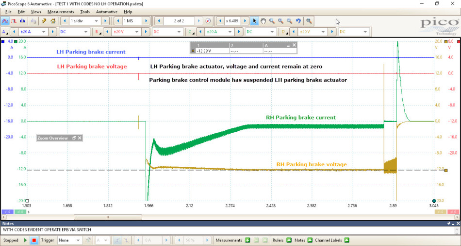
Initially both actuators functioned correctly drawing approx. 17.5 A until the Parking Brake Malfunction error message appeared. This occurred when releasing the parking brake, not applying. With the fault now present, continual operation of the parking brake confirmed no current flow to the LH parking brake actuator, RH operation was normal. A brief check of the fresh fault codes confirmed the return of:
The PCM and ABS modules also reported U codes, indicating communication errors with the EPB module. At this stage we can attribute these codes to missing messages from the EPB module as the parking brake malfunction results in communication anomalies generating multiple warnings for the driver.
The action plan is predominately governed by accessibility and probability. Based on the fact the LH parking brake actuator is repeatedly indicated as the offender, we need to qualify the actuator circuit.
With the fault present on the vehicle, the current flow and voltage supply to both RH and LH parking brake actuators was captured using breakout leads and two current clamps connected to PicoScope.


Below, PicoScope live data confirms there is no voltage supply or current flow to the LH parking brake actuator. However peak inrush current to the RH actuator exceeds 20 A.
Using the PicoScope 4425 model with floating inputs (https://www.picoauto.com/library/training/voltage-drop-techniques-introducing-floating-inputs) we have the advantage of measuring across the brake actuator Channel B red & D yellow to confirm the presence of both power and ground simultaneously during actuator operation.
Given the fault was becoming easier to reproduce, the fault codes were once again erased and the parking brake operated whilst monitoring voltage and current to both actuators. The theory here was to catch the exact moment the fault appeared and identify what events were taking place in the parking brake circuit.
Below I have revised all the input ranges and test lead orientation at both brake actuators to provide a clearer view of voltage and current during EPB operation.
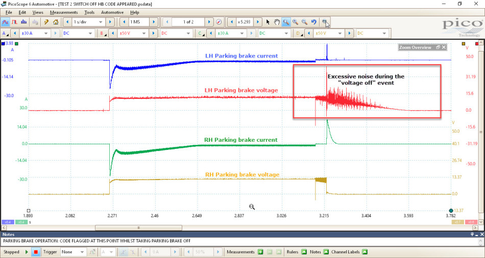
Above we have captured one of those rare intermittent glitches which is directly responsible for our EPB fault codes. Closer analysis reveals a number of concerns with the voltage supply and current flow through the LH parking brake actuator.
Looking at the zoomed waveform above we can clearly see excessive noise 41 V peak about the supply voltage to the LH parking brake actuator Channel B red. The effect of such noise results in sporadic induced current flow, a 14 A peak at the point of power off to the LH parking brake actuator during the release function.
If we compare Channel B red to Channel D yellow, notice how the voltage supply 12.9 V peak instantaneously drops to near zero volts at the point of power off, Channel D yellow, after the parking brake mechanism has released its grip on the brake pads.
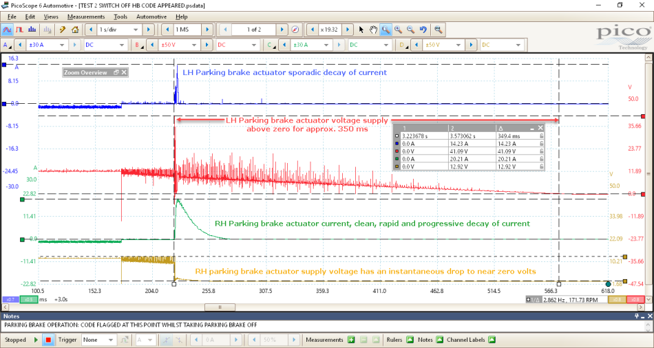
Here the induced current flow at 3.22 s, 20 A peak for the RH parking brake actuator Channel C green has a rapid increase and controlled decay compared to the LH actuator Channel A blue. Whilst the formation and decay of this current is a clue to the parking failure, it is most certainly a symptom and not a cause. I will cover the phenomena surrounding this current at the end of the case study, post fix.
Our Parking brake control module suggests the LH parking brake actuator has a short to battery positive. This can be seen in the time taken for the voltage on Channel B red to fall to zero volts after the parking brake release function has completed. The LH actuator voltage decay time measures approx. 350 ms compared to the RH actuator at approx. 15 ms, therefore interpreted as fault code 71424 - Left Parking Brake Motor voltage supply - Short to Plus.
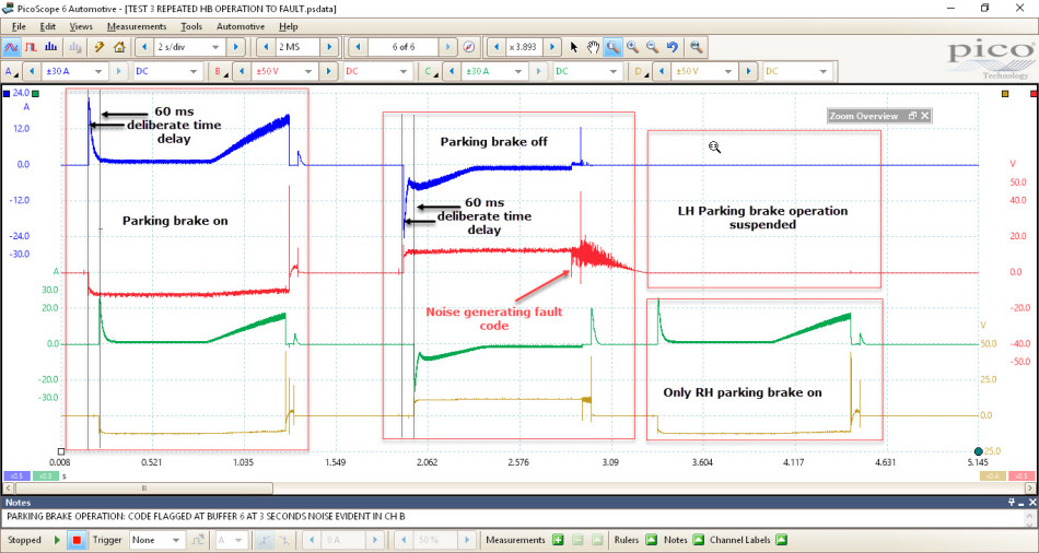
I also mentioned in the Technical Description that the LH parking brake actuator appeared to lag behind the RH. The voltage decay time would also support this symptom, however there is a characteristic time delay built into the operation of the parking brake. The waveform below confirms a 60 ms time delay between the operation of the LH and RH actuators in order to minimise the impact of inrush current on the parking brake control unit relay contacts and the generation of Electromagnetic interference (EMI).
I guess the question raised from the above capture is where is the electrical noise being generated, causing the parking brake fault code and suspension of the LH parking brake actuator? Below I have changed Channel C green and Channel D yellow to the capture the voltage and current flow through the power supply wire to the EPB module.
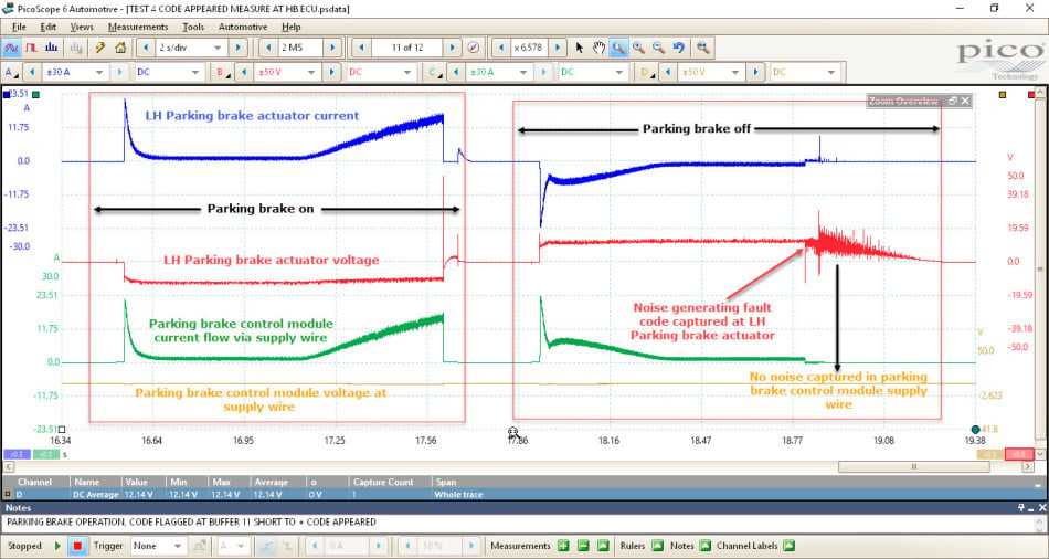
Again we can see how the noise generated during the release stage of the parking brake is evident at the LH parking brake actuator, but not in the supply wire to the parking brake control module! This is the same wire that will ultimately supply power to the LH parking brake actuator via the internal relays within the control module. Thinking this through, the EPB module receives a power supply from the vehicle fusebox which in turn will supply the brake actuator via an internal relay. The earth return for the brake actuator once again will pass via an internal relay inside the EPB module and onto chassis ground. A visual inspection of the EPB module chassis ground point confirmed no areas of concern and so at this point a decision has to be made on what we know.
Only during the release function of the parking brake do we see intermittent excessive noise which generates a fault code within the EPB system referring to the LH parking brake actuator.
The application of the parking brake does not generate noise or induce a fault code.
The LH parking brake actuator has been replaced. Had the actuator been responsible for the noise e.g. arcing motor brushes, the noise would have been present during parking brake on and off.
The circuit between the EPB module and LH actuator is good based on the values compared at both the module and actuator.
The power and ground to the EPB module are good with zero noise on the power supply to the control unit when the fault occurs. With hindsight I wish I had measured the noise on the ground line to the controller simultaneously!
Based on the summary above the EPB control module was replaced as the source of our noise during the parking brake release function.
With the EPB module replaced using a device containing the correct suffix, part number 4H0 907 801 L, stress testing was once again carried out to confirm a fix.
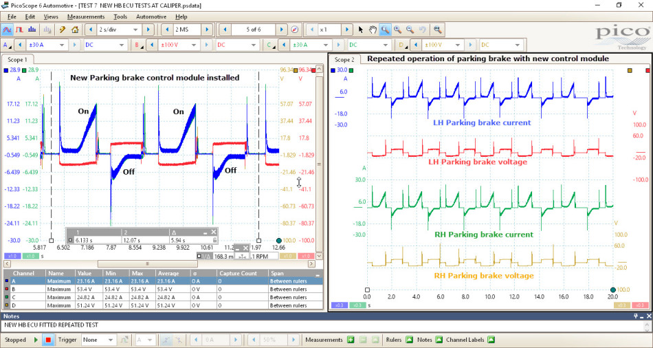
The scope view on the right highlights the number of parking brake cycled events during stress testing. Approximately six on/off events were captured over six waveform buffers, which equals 36 parking brake operations over the two minute period (a timebase of 2 seconds per division [2 s/div] gives 20 seconds of data per waveform buffer, and six buffers results in a total collection time of 120 seconds), without fault. Note also how the peak voltage and current measurement values for each actuator are now much closer to one another than with the previous EPB module.
The scope view on the left has all channels overlaid on top of one another so as to reveal any variation between voltage and current. Theoretically the LH and RH actuator voltage and current waveforms should align perfectly if the EPB module is performing correctly, or should they?
I mentioned previously how we captured a 60 ms time delay between the operation of the LH and RH actuators in order to minimise the impact of inrush current on the parking brake control unit relay contacts, and the generation of EMI. This does make perfect sense, however, the replacement EPB module behaves differently during the operation of the parking brake. Both parking brake actuators are activated at precisely the same time during both application and release, but the current flow to the LH actuator is switched off 40 ms before the RH actuator during parking brake application and 60 ms sooner during parking brake release. The waveform below highlights the 40 ms time difference during parking brake application only.

This is most certainly a complete change in the strategy of the parking brake control system software for the new EPB module and could also indicate a modification to the internal design hardware. Could this be what the technical literature was referring to by the suffix change we discussed earlier? I guess we may never know but any feedback would be most welcome.
Happy in the knowledge we have a fix, the temptation to dismantle the original parking brake control module was too much to refuse. Thanks to the hardware team here at Pico the control relays were carefully removed from the EPB module PCB and inspected under the microscope for signs of wear. The results below speak for themselves.

Below you can see the operation of the relay contacts thanks to a short video that reveals the witness/burn markings on the surface of the relay contacts due to arcing. These burn markings are responsible for the noise evident in the LH brake actuator voltage during the release of the parking brake.
Earlier in this case study the formation and decay of the induced current during parking brake operation application & release was highlighted as an area of concern but a symptom rather than cause. Here we need to understand the momentary events that take place within the EPB module during the power off stage of operation. In order to halt the parking brake actuator DC motor, both motor brushes are momentarily connected in such a way as to ensure no potential difference exists across the commutator. Depending on the internal configuration of the EPB module, both motor brushes are connected to one another, to chassis ground or across a load resister via the EPB internal relays. The momentum of the DC motor is therefore reduced thanks to the effects of electrical braking given our DC motor has momentarily become a generator, hence the creation of the induced current. The nature of generating current has the desired side effect of loading the armature so reducing its rotational speed, this is regenerative braking in action. The waveform below displays the rapid generation and progressive dissipation of induced current thanks to a new EPB module.

In order for the generated current to dissipate both rapidly and progressively, the circuit integrity throughout the DC motor brushes, EPB relay contacts & termination point must be efficient. Previously the burnt EPB module relay contacts introduced a high resistance where the current generated from the actuator during electrical braking attempts to jump across the worn contacts, introducing arcing. In this scenario a varying potential difference will continue across the motor where the voltage will remain above zero for longer than expected, hence the fault code, Left Parking Brake Motor voltage supply - Short to Plus.
One final point to mention with reference the serviceability of the parking brake actuators. You may remember the LH parking brake actuator had been replaced using a pattern part. I could not help but notice how the LH actuator peak induced current reached approximately 4 A yet the RH original actuator achieved 5.25 A. Whilst this may not be relevant, could this be an indication of the efficiency of the components used within the LH actuator? Food for thought yet again!
The ability to capture high frequency noise prior to fix Channel B red highlights the need for a high-performance scope where such anomalies occur. Without sufficient bandwidth and sample rates such high frequency noise would not have been displayed so leading to a prolonged and ill-informed diagnosis. Once the repair had been completed, PicoScope also revealed finite detail surrounding the operational characteristics of the parking brake control system that we are not gifted when it comes to technical data. The post fix analysis becomes a form of reverse engineering that can only be concluded when measuring component operation in real time with infinite detail at lightening speeds, all of which require PicoScope.
For more information surrounding the Electromechanical Parking Brake from the VAG group refer to Self-Study Program SSP 346.
AndrewBew
April 21 2020
Awesome way of expression. Keep it up!
Diankas red
August 30 2019
Приветики ребята!
Tony
August 01 2019
I have a VERY similar problem with a 3yr old VW Golf SV Mk 7: SE 1.4 TSI, 125 PS. The EPBs have seized 4 times, but the garage refuses to accept there’s an ‘inherent fault’. I need to find an automotive diagnostic engineer who can carry out the same forensic analysis. Can you tell me who carried out the work on the Audi?
Andres
November 16 2018
Excellent diagnosis, thanks for sharing !!!
BOGDAN BODNARESCU
October 25 2018
Now send this to Audi !
Tom Denton
October 25 2018
An absolute pleasure to see such a detailed and logical diagnosis procedure. Great work Steve and thanks for sharing.
Tom


