PicoScope 7 Automotive
Available for Windows, Mac, and Linux, the next evolution of our diagnostic scope software is now available.
Automotive guided tests
Library of examples on how to perform tests when using PicoScope.

Training
Our collection of training videos, articles, guides and information on training courses.

Waveform library
The Waveform Library is a global database of waveforms uploaded by PicoScope users.

Case studies
Real-life case studies show how the professionals use PicoScope to diagnose vehicle faults.

A to Z of PicoScope
Detailed description of various PicoScope software and hardware features.

Videos
Training resources and demonstrations on PicoScope and the Automotive Diagnostics Kit.

Newsletter
Archive of our monthly Automotive Newsletters.

Documentation
Download manuals, brochures, posters, and training materials.

Reviews and awards
Accolades for the preferred diagnostic tool for service centers and vehicle manufacturers.

| Vehicle details: | Mazda CX-3 |
| Symptom: | DAB Amplifier |
| Author: | Ben Martins |
We keep talking about having a diagnostic process but it is so important to remember this when coming up with those unknown faults we don’t see every day. Not only can this keep you on the right course but having a firm action plan can save you time. This doesn’t have to be my process nor anyone else’s but as long as you have one, that is the important thing. Bear in mind this is the process I used whilst I was with Toyota, which now seems like a lifetime ago…..

Are the details you’ve got on the job card correct for the vehicle you are being presented with? Sounds obvious I know but with so many variants of the same model this can often get overlooked. For instance, with this particular car there can be options for Bose sound system, Lane Departure Assist, Adaptive Cruise Control, Halogen or LED lights, with or without satellite navigation (satnav), with or without centre screen, the list goes on.
For this model the key factors we needed to know were, the vehicle has: centre screen, Bose sound system and satnav which also comes with voice recognition.
The customers have all the answers! Talking to them could give you the “golden piece” of information. It may be something simple like “the lights only flicker when it’s raining”, but what if you didn’t ask and all your testing is done in the workshop which is hopefully nice and dry you will get, “no fault found”. The next time it rains the customer will be back on the phone to you.
When does it happen? How often? Has it always been there? If not, when did it start?
Below are the symptoms as described by the customer:
When attempting to switch the radio on by using the touch screen interface, the radio button is highlighted but the menu cannot be accessed. The same condition is met when trying to use the command wheel in the centre console.
No audio or output to any of the speakers including satnav, Bluetooth or voice recognition. Volume also doesn’t work and when adjusting settings for treble, bass, left and right or front and back, the selection can be made but it reverts to the original position after a couple of seconds.
The classic saying of, ‘if it isn’t broke, don’t fix it’ springs to mind! But in all seriousness how can we begin to fix something if it’s not behaving in the way the customer described it? As frustrating as intermittent faults are, sometimes it’s better to leave it alone until it manifests more frequently or if we can get authorisation from the customer to carry out extended road testing. We could stand back and throw parts at it in the hope that when the customer picks the car up they won’t come back but the likelihood is they will be in the next day and now you’ve got to do it all for free. This is where the customer interview can help. If they can accurately describe how the fault occurs then replication should be straight forward.
With this case it was pretty straight forward. The fault was always there no matter what the condition of the vehicle. Ignition on, engine off, engine running, stationary or moving it was a permanent fault. Great – should be easy right??
There is always a place for serial diagnostics and it should never be overlooked. It can offer vital pieces of information to add to the puzzle and if there is freeze frame data this can give you the vehicle condition just before and after the fault occurred. This is especially useful when dealing with intermittent faults.
The Mazda had no warning lights on the dashboard yet it definitely has a fault. Carrying out a global scan of the vehicle revealed no fault codes, but there was communication to the Connectivity Master Unit (CMU). It is the CMU that gathers the inputs and outputs to control the infotainment system. Another useful tip here is to take note of the ECU’s detected. You may not have any fault codes if the ECU potentially at fault, hasn’t been picked up during the global scan.
This can only really be done properly by going to the vehicle manufacturer's (VM’s) site. It is definitely worth doing as the fault you could be chasing could be rectified by a software update that you are not going to find using any diagnostic methods! Doing this could save you a lot of time.
The Mazda had neither software updates available nor were there any technical bulletins for a similar fault.
This can be done with product knowledge if you work specifically with one brand but for those of us that can’t store all this information from every manufacturer then the best place is to find it is once again on the manufacturers’ site. You can use alternatives but I find that if you want to know what you’re dealing with the VM site is the place to go.
The new car features section is normally where you would find everything you need to know about the how something works. So from here I wanted to understand how the system operates and what controls the audio in the vehicle. From the VM site I found that the CMU controls the entire infotainment system such as communication between mobile devices and Bluetooth, also the sending-receiving of both video and audio signals from units related to the entertainment system.

Now we can see how the inputs and outputs for the audio system work.
The Tuner and Amp Unit (TAU) is actually responsible for the audio output to the speakers based on a control signal sent via a local CAN network from the CMU. Getting a better idea of the network itself is important at this point, which is where the CAN topology can help to see how it’s all connected.


As you can see from the first image we have a list now of all the ECUs that should be on the network. Our earlier investigation into vehicle ID now comes into play as some ECUs such as Blind Spot Monitoring may not be relevant which could lead us thinking the problem lies within a system that isn’t actually connected to the vehicle. Our area of interest from a system description is the Connectivity Master Unit. This also highlights a local CAN network of 3 or 4 ECUs with terminating resistors in both the TAU and the CMU. What is strange is how come I can’t see these ECUs on a global scan? Reading through some further technical information I find that there is an On-Board Diagnostic function within the CMU. The description is as follows:
On-board diagnostic function
The on-board diagnostic function consists of the following functions:
This function requires access to a hidden menu which is where using the VM’s technical site is so important. You could spend hours scrolling through webpages but these days the information is there and usually at a fairly reasonable cost. In my experience technical sites range between £5 and £12 per hour, so be specific with what you are looking for.
In this instance you access the menu by holding the command switch buttons Volume, Audio and Favorite for more than 2 seconds. From here you can scroll through the menus till you find Read CMU DTC. It is here we find the missing link as a fault code has been generated U0184:00 - Communication error with tuner and amp unit (TAU).
This is where having gathered as much information as possible becomes helpful as we can now list the likely issues.
Although this might seem a waste of time as surely by now it’s just, get stuck into the car, but this can really keep things focussed when time is against you.
From the list above there are some easy ones we can check straight away, power and ground.
If we have an ECU with no power supply then it is effectively offline and therefore won’t be seen by the other ECUs. ECU malfunctions do happen but I tend to leave them to very last. No-one likes making the call on an ECU so let’s cover all other options first!
You could stick with the manufactures diagnostic route at this point and there is nothing wrong with that, however, there is a problem with that route. If you were to follow it through you would put a TAU on the vehicle and the fault would still be there. For me I would much rather be a little more open minded and with a thorough understanding of how the system works come up with my own action plan.
Looking at locations, the TAU is by the driver's side kick panel which is easy to get to. Power and grounds need to be checked and, as we have a “communication” DTC, I also wanted to see the network signal.
This can sometimes be tricky and you just sometimes have to do what is necessary. With this particular case we will have to adopt back-pinning, which is regarded as intrusive testing. No need to pierce the insulation though as the plug hasn’t any waterproofing seals. Therefore, the back-pinning probes can be inserted carefully between the plug casing and the terminal.
Starting with supply, I want to see if the ECU is receiving power and has an earth. A meter would be adequate, but as I had PicoScope out already I have a way of recording all of my information and can observe both tests at the same time. With the correct wiring diagram and the ignition turned on I have battery voltage at the supply wire and 0 V at the earth.
Next on the list is wiring.
Now we know that the CMU talks to the TAU via a CAN network so this seemed to be a likely cause from our action plan.
Reading the description further its detection condition is ‘the connectivity master unit (CMU) cannot receive a CAN signal from the tuner and amp unit (TAU) for 5 seconds or more.’
Does this mean the ECU is not responding or is it offline, is there an issue with the CAN wiring? We know this is a small CAN network with two terminating resistors which are likely to be 120 Ω. In order to measure this correctly the power supply needs to be removed so with the customers settings saved the battery negative was removed. Consulting a wiring diagram I was looking for the easiest way onto this network and discovered a little check connecter which sits just above the OBD port. I’m not entirely sure the purpose of this connector but it meant I could be certain that there are only 2 wires at this plug one CAN H and one CAN L. A quick resistance measurement saw the 60 Ω expected from CAN providing this network had two 120 Ω terminating resistors on this network. With the wiring in front of me the next step was to physically look at the packets of data for integrity. Attaching Channel A of PicoScope to CAN H and Channel B to CAN L meant we could see both sides and make sure data is being transferred. Even with serial decoding we cannot verify which ECUs are sending or requesting data but we can see if it is there for a start. I was only looking for signs of communication to begin with so a longer time base was used.
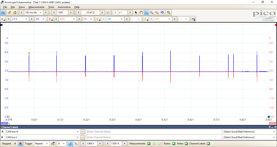
At first glance you could say that we have data present and it is being seen in both CAN H and CAN L but once you start to zoom in there is something not quite right with the signal.

What stands out immediately is CAN Low. As you can see from the image above at point 2, the idle voltage starts in the middle of the data packet rather than being pulled down from the 2.5 V we typically see in most CAN networks. However, what is interesting is that when the network is broadcasting data, the network adjusts to where we see CAN H between 2.5 V and 3.5 V and CAN L at 1.5 V and 2.5 V.
PICO TIP – If two rulers aren’t enough then add a reference channel and match the vertically offset with each other. This will give you two other rulers to play with without having the other disrupting your view (I can’t take any credit for this tip – my thanks here go to Alan!).
Whilst I was looking at this information, I could hear Steve Smith’s voice in my head – “Maths is cool…..” so, I decided to look at the physical layer.
Using the Tools menu and selecting Maths, I used the A-B preset to allow me to look at what the ECUs would be seeing once they have seen the data packets, the physical layer. There is an ongoing forum post surrounding Maths channels and their application. If you want to know more head to https://www.picoauto.com/support/topic21311.html

Now, this is why CAN is regarded as fault tolerant. Despite the fact we have an issue with the idle voltage of the network when we perform A-B we see that it switches between the 0 V and 2 V that we expect to see. As both side of the network are affected by the same issue, when we take away one from the other it cancels itself out. When dealing with CAN faults I try to use both A-B and A+B. Due to CAN’s tough nature, faults don’t normally appear that easy but when using both these maths channels they help with finding the fault.

If we were to add CAN H and CAN L together we should see that, whatever condition of the network if it is in idle or transmitting, it should remain around 5 V. There are two posts on the forum that talk about using Maths channels to catch CAN faults, these can be found here:
We already suspected a voltage issue but by using some simple maths we can quickly see the area of interest.
Now would be a good time to recap!
To continue with the diagnosis, I believe we are looking at an ECU that is corrupting the CAN network. The nice thing about this fault is that it is on a very small network and therefore shouldn’t need too much dismantling but sticking with our action plan list the likely ECU is going to be the TAU. Firstly, I wanted to see what happens if I remove the power supply.
Simply removing the plugs to the TAU saw the network to rectify itself.
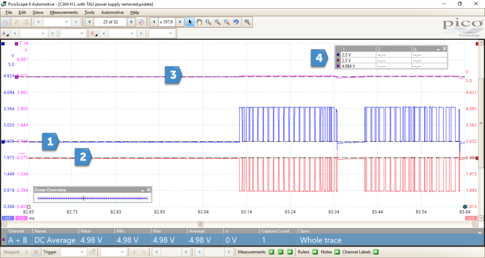
As you can see above we have the expected signal for the two CAN lines. When at idle the network voltage sits nicely at 2.5 V and when data is transmitting the voltages are pulled high or low. I’ve also included the A+B maths channel which is sitting around the 5 V mark even when messages are being transmitted. This to me proves that the fault lies within the TAU, but does this mean we are ready to throw an ECU at it?
This is a tough call and one which I certainly don’t like to make without being 100% certain. In this instance there was the luxury of having two identical vehicles, one of which had no fault with the audio system. Double checking that the specifications were all the same, I decided to fit this TAU to the faulty vehicle, with the hope it was all fixed. No such luck.
With both TAUs out we felt that the ultimate test was to fit the suspected faulty TAU to the known good vehicle and, what do you know, it works! Having this option is of a donor car is a luxury I know, but there are ways around this as we continue our journey.
With this new knowledge that the TAU isn’t at fault we turn our heads back the drawing board. Looking back at the inputs and outputs of the TAU and keeping it a simple there were two other inputs to the TAU, the AM/FM aerial and the DAB amplifier. Reading the technical information on these two devices it was established that they both carry a power supply. We know there is something effecting the voltage level of the CAN network could one of these be responsible for this?
This next step is one that might be useful when you haven’t got a donor car. Prior to condemning an ECU, remove any other connectors but keeping the power supply and communication wiring to the ECU. ECUs all rely on inputs and outputs and by removing them can help identify if either could be causing a fault. In this case removing both of the aerials saw the network voltage was re-established to 2.5 V but still no functionality from the controls. A cycle of the ignition saw all volume controls restored and static from the speakers.
Determining which one was at fault was fairly straight forward, plug each one in and see what happens. It was found that when reconnecting the DAB amplifier antenna the system shut down and the network voltage was back down to 1.9 V. Consulting the repair manual in order to test the DAB aerial you had to see 8 V at the amplifier connector in the tailgate. The diagram is a little confusing to say the least but by disconnecting and back probing the connector I could see that 8 V was present proving the ECU was sending the correct signal out and therefore, condemning the amplifier. Fitting a new amplifier fixed the fault and to confirm we made sure the DAB radio worked.
This is often an overlooked part of the repair but it is important to make sure you have the evidence to prove that the fault is fixed. Below is a capture of the CAN network with the new DAB amplifier fitted.
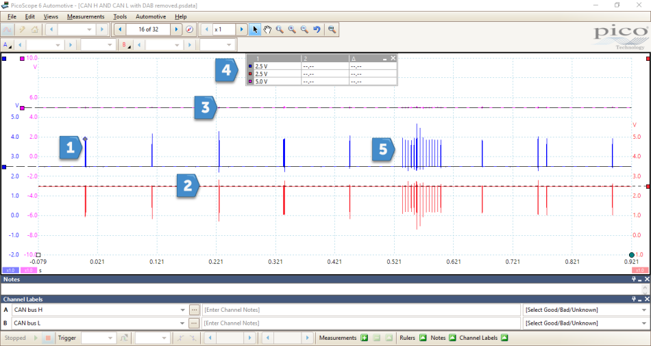
From the new capture we can see that the A+B maths channel remains consistent at 5 V, using the rulers we can see that the network idle voltage is at 2.5 V and we seem to have more messages on being transmitted. Volume and sound settings can also be adjusted all fault codes have been erased from the CMU memory.
This isn’t going to be a common fault and one that has numerous points that could trip you up but it goes to show that a good diagnostic process can lead to success.
Ben Martins
December 21 2018
Thank you all for your kind words.
With regards to your comment Peter, I know I had the luxury of a donor vehicle but there is a section referring to what to do if you don’t. Removing the inputs and outputs to the TAU was how we found the fault and using this tip will ensure you don’t just replace an ECU. I apologise Peter if this section wasn’t clear. Thanks again all your comments and I hope this helps in the future.
BOGDAN BODNARESCU
December 20 2018
Amazing fix!
Dave Baxter
December 20 2018
Possibly a shorted Tantalum decoupling cap’ in the DAB antenna, or similar supply loading issue. Nice write up.
Peter Hicks
December 20 2018
A very interesting case of fixing a fault by swapping parts off a donor vehicle,not many people would be able to do that in the real automotive world,
It,s not everyone that has the facility to do so.i suppose thats why its good to have reference wave forms,but in my experience you can never find the reference wave form that is relevent to fault that is being investigated.
IAN DURSTON
December 20 2018
GREAT CASE STUDY, I’VE NOT SEEN THAT FAULT IN A CAN BUS SIGNAL BEFORE, MANY THANKS. IAN


