PicoScope 7 Automotive
Available for Windows, Mac, and Linux, the next evolution of our diagnostic scope software is now available.
Automotive guided tests
Library of examples on how to perform tests when using PicoScope.

Training
Our collection of training videos, articles, guides and information on training courses.

Waveform library
The Waveform Library is a global database of waveforms uploaded by PicoScope users.

Case studies
Real-life case studies show how the professionals use PicoScope to diagnose vehicle faults.

A to Z of PicoScope
Detailed description of various PicoScope software and hardware features.

Videos
Training resources and demonstrations on PicoScope and the Automotive Diagnostics Kit.

Newsletter
Archive of our monthly Automotive Newsletters.

Documentation
Download manuals, brochures, posters, and training materials.

Reviews and awards
Accolades for the preferred diagnostic tool for service centers and vehicle manufacturers.

| Vehicle details: | Chevrolet Suburban |
| Year: | 2009 |
| Symptom: | Engine misfire, MIL on |
| Author: | Mario Rojas. Great Bear Automotive Miami, FL. Started career in 2013. ASE Master Certified, L1 Certified. |
One of the most rewarding aspects of our careers is when we can apply newly learned techniques, thus improving our diagnostic process, all while enhancing the way we interact with our clients throughout the diagnosis and repair of their vehicles. Not only will it build credibility with our clients, but diagnostic efficiency and upgraded strategies allow a technician to only disassemble if it's absolutely necessary.
I received a work order for a misfire and MIL concern on a 2009 Chevrolet Suburban 5.3L.

2009 Chevrolet Suburban 5.3L
As I’m walking out to the parking lot, a plan of attack is already contemplated. I usually will follow the same exact plan of attack when it comes to any misfire. As I see it, there's a fork in the road on a misfire strategy. Road number one leads us down the path of a mechanical failure/cylinder wash possibility. Road number two leads us to all of the other possibilities; air/fuel concerns, ignition, electrical, etc. In some cases, the injector of a misfiring cylinder may be disabled, so as to prevent cylinder wash in the case of weak/no spark conditions (something I always keep in the back of my mind).
Nonetheless, my first step is always to rule out an engine mechanical/cylinder wash possibility. Not everyone might agree with that, but I've decided to make it my first step because engine mechanical failures can be at times some of the easiest things to verify, and their repairs can be the most expensive of all misfire causes. In the past, I would diagnose a misfire by checking for spark first, then fuel, then compression, only to find out that mechanical integrity was the issue. After all, that digging, many times a client will hear about what is necessary to fix that mechanical failure, and decline the repairs. I’ve since made it part of my misfire diagnostic strategy to ALWAYS rule out mechanical health, or lack thereof, FIRST.
Luckily, this vehicle (not all) allows for a "clear flood” mode, in which upon KOEO (key on, engine off), WOT (wide open throttle) conditions, the ECM will default to an injector pulse "cutoff" across all cylinders. Thus allowing for only compression strokes to occur when attempting to crank the vehicle over.
What I am listening for is uniformity between each sequential compression stroke (theoretically each cylinder should load the starter by the same amount during each compression stroke). In other words, by inhibiting vehicle starting, I’m listening to the relative compression between each cylinder via the rhythm it produces during starter engagement. Mind you, this test really shines when a single cylinder or two lack compression. A failing result will be an uneven rhythm. As is the case with our vehicle.
Now I have been burned by a low compression cylinder on an eight-cylinder engine by trusting my ear, so I always follow up with a scoped cranking amperage test. But it was safe to say we already have a sense of direction, at the parking lot, before I even saw the mileage of the vehicle.
Once I heard the failed clear flood mode cranking rhythm, I released the throttle, the engine started, and I could hear and feel a "dead" misfire, along with the MIL on, verifying both of the client’s concerns, before entering the bay.
Once inside the shop, of course, my next step was to document the DTC, a single P0306 - Cylinder 6 misfire. Nonetheless, I wanted to verify not only whether the ECM cylinder identification was telling the truth, but also if my ears were being honest as well.
My ears WEREN'T fooling me!
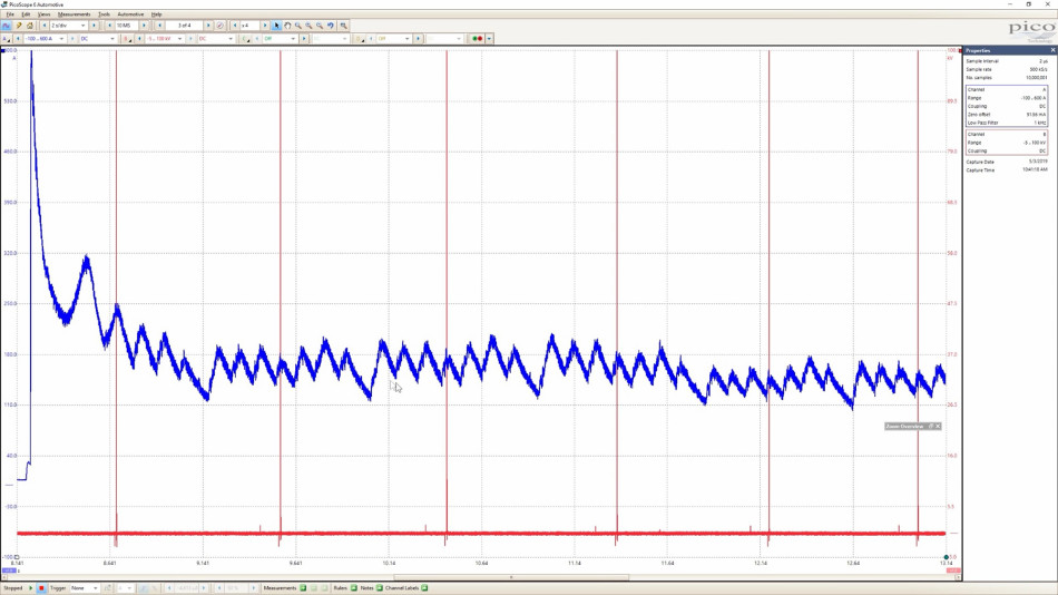
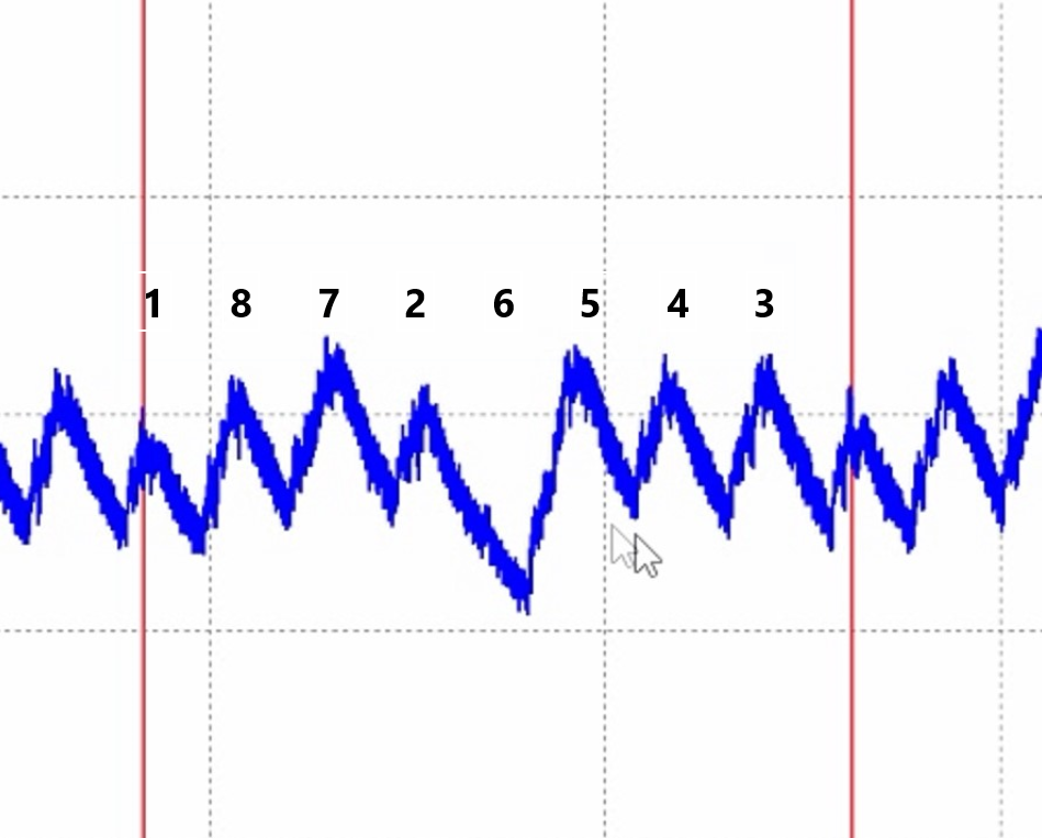
This capture (Figure 1) is synced to ignition coil number one, by way of a secondary ignition lead, and the cranking amperage is acquired with an amperage clamp around a battery wire. The RC (Relative Compression) test is a visual representation of the test I did listening to the engine's cranking rhythm. The firing order sequence (Figure 2) will be necessary to decipher which amperage peak (TDC) belongs to which cylinder.
Looking at the waveform (Figure 3), it's apparent that compression within cylinder one is not looking too good. Plus we have a dead number six-cylinder, although our scanner has coded a misfire for only cylinder number six. Soon we'll see the importance of conducting the same tests multiple times.
Of course, it would be foolish of me to assume that only because we have a concern with lack of cylinder compression, that it is necessarily an engine mechanical failure. My next step, when confronted with a failed RC test, is always to rule out cylinder wash, which can easily be caused by an overly generous or stuck open injector, or even a weak ignition spark that will not burn the injected fuel sufficiently, or even a lean condition in which the ECM has responded by compensating with more fuel. The accumulation of unburnt liquid fuel within the cylinder and in turn the wash down of that cylinder ensues.
Every piston has a thin protective oil film between its rings that keeps the combustion chamber isolated from the crankcase. “Cylinder wash” is when liquid fuel dissolves that protective oil film, resulting in loss of ring seal, combustion pressures and raw fuel entering the crankcase, cylinder wall/ring damage, and in severe cases, bearing/piston failure.
I usually will quickly smell the dipstick, and in extreme cases, this will allude to cylinder wash. No fuel was sensed at the dipstick, and I also hooked up a piezoelectric sensor (also known as delta, differential pressure, pressure pulse, a device I’ve never utilized prior to that training class, which reacts to changes in pressure and is highly sensitive) to the dipstick inlet. I could not find any sign of cylinder wash or concerning compression leak into the crankcase for that matter. (Unfortunately, I failed to save that capture).
NOW a mechanical integrity issue has been deduced. At this point, any time spent on road number two would be in vain.
Now, I could have easily stopped there, having ruled out a lower end sealing issue, sent out the heads for service and been done! Right?
Not so fast!
We are still synced to number one ignition using a secondary lead, with the high amperage current clamp closed around the battery ground wire, and the piezo sensor at the intake manifold, in place of the brake booster. We're ready for testing.
For those who've never used a piezo sensor, this sensor reacts to changes in pressure, as mentioned earlier. In the same way, a relative compression test measures theoretical compression differences across all cylinders, the intake pressure pulse test measures theoretical intake pull differences across all cylinders. This sensor may also be used for exhaust pulses as well, but that test will not be demonstrated in this case study.
Depressing the accelerator pedal all the way, causing a WOT, I attempted a relative compression test. To no avail of course, since there's a lack of air restriction a closed throttle provides. The intake pulse waveform was useless without that restriction.
I had a cap nearby that usually accompanies a smoke machine, so I placed it on the throttle body (Figure 4) in order to recreate the air restriction as I attempted a second capture.

Figure 4
To facilitate analyzing this waveform (Figure 5), within the PicoScope software, the user can set up vertical rulers, partitioned however they see fit. In my case, eight partitions (one for each cylinder) keeps everything easy on the eyes. Using a piston chart created by non-other than Scott Shotton (Driveabilityguys.com) is also utilized in order to observe each piston direction and its respective stroke/cycle anywhere within its range.
The fault could not be clearer! But of course, the ability to acquire the waveform, and pinpoint the fault only emerged because of what I had learned in the classroom. Prior to taking Brandon Steckler's “Pressure Acquisition & Analysis: From the Inside Out” class, I had never laid eyes on such a waveform, nor what was required to acquire and dissect it.
This is the importance of conducting the same test several times. It is quite obvious that compression at cylinder number one is perfectly fine at this point. One shouldn’t put all their eggs in one basket, neither should we commit to only one test! ESPECIALLY the cranking amperage test, as there are MANY factors that can affect its results. In reality, up to this point, I’ve conducted the relative compression test three times. The first test was the synced relative compression test documented here. The second test was with my delta sensor at the dipstick, vindicating all the piston rings' sealing integrity (that I forgot to save). Finally, the third relative compression test is this one, which includes the delta sensor measuring intake vacuum pressure differential pressure, that we are about to dissect.
At first, I'll admit, the piston chart was a bit daunting. My head was spinning! With a bit of practice, and a couple of rule of thumbs, it became invaluable.
Let’s overlay some data to clarify what we are looking at.
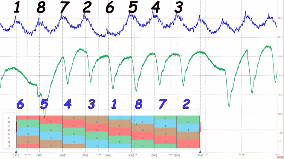
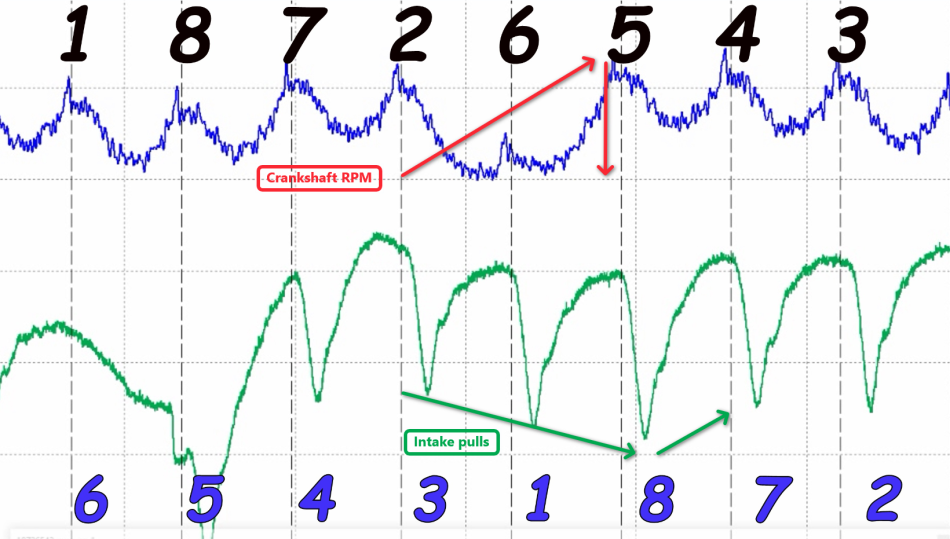
Starting from the top of the waveform (Figure 6), each cylinder TDC-C (Compression) peak is marked in BLACK on our blue cranking amperage waveform, commencing from ignition sync; cylinder number one, and continuing on in the firing order sequence. Beneath that is our green intake pulse waveform, which also follows the firing order, but instead begins with cylinder number six (cylinder number one's companion cylinder).
In our amperage waveform (Figure 7), the cylinder number one TDC-C peak lines up at the beginning of the red “P” Power cycle, at the very top of our piston chart. That commences our four-stroke cycle and continues horizontally onto a brown “E” Exhaust stroke rectangle, a blue “I” Intake stroke rectangle, and finally ends with the green “C” Compression stroke rectangle. Thus completing the 720 degree-Otto cycle for cylinder number one.
Since we are observing an intake pulse waveform (Figure 8), we can see each intake pull lining up with its corresponding cylinder upon EVC (Exhaust Valve Closing), keeping in mind that during our exhaust stroke, the intake valve opens, overlap (both valves open) occurs, we surpass TDC-E, then EVC takes place, allowing for our intake pulls to occur.
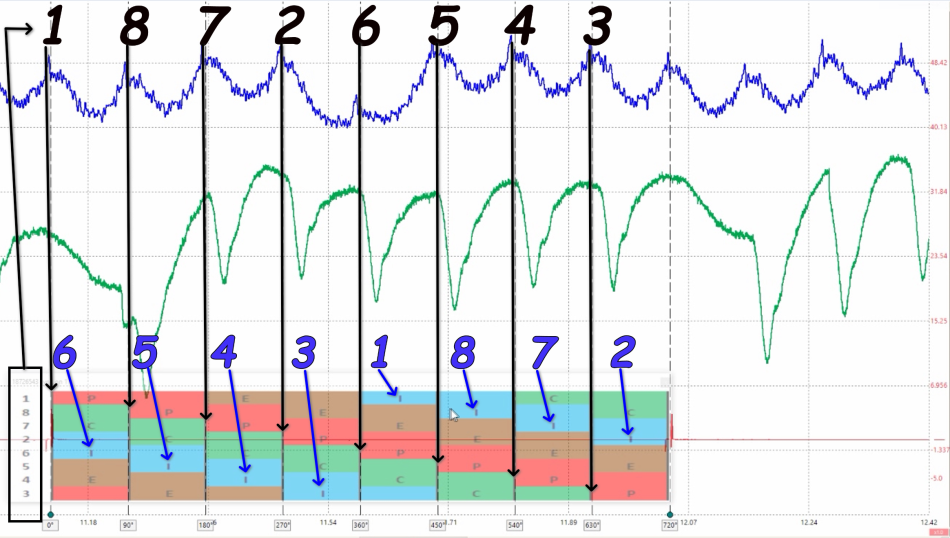
Still synced to cylinder number one TDC-C (at the top-left of the piston chart), we are able to see that its intake stroke commences 360 degrees after its TDC-C. Sticking to the firing order(descending from 1 at the left of the piston chart) we can go ahead and fill in each of the intake pulls (BLUE), respectively. All intake pulses have been circled in blue so that we can make it easier to see where each of the numbered intake pulls vertically line up with the piston chart below it, one by one, following the firing order.
We have now identified all our TDC-C events, as well as our respective intake vacuum pulse sequence.
One thing we should always keep in mind is, never forget the suspect!
We’ve established that number six is our suspect cylinder. The number ONE question should always be “What is our suspect doing?” Is the suspect cylinder piston ascending or descending? On which stroke? Ascending; compression or exhaust? Descending; power or intake?
A ton of headaches will be avoided if we simply do not lose sight of our suspect!
At this point it should be pretty obvious, the nonexistent intake pull upon number six EVC. Absolutely zero negative pressure is occurring. Followed by a "deep pull" upon number five EVC, which I had no explanation for. After consulting with Brandon, it turns out that this "deep pull" is a result of the sensor we are using, a Delta sensor. The intake became "stable" during the absent intake pull, the sensor “relaxed” and was followed by a "rapid" change in pressure the number 5 EVC, resulting in a seemingly "deep" pull, which wouldn't have occurred with an absolute sensor (a WPS500X, for example).
One more thing to notice is the effect crank rotation speed has on the intake pulse waveform (Figure 9). During a low/no compression cylinder event (number six), the crankshaft rotation momentarily speeds up, there's no compression to slow it down until it’s confronted with a good compression event, from cylinder number five. When you observe the intake pulse directly below that event, you can see the intake pulse start to appear as if each cylinder is pulling more and more as the crank RPM speeds up. Then, as the crank speed slows down, the intake pulse appears to imply that each cylinder is pulling less and less.
Anywho, our concern remains with the lack of intake pull upon cylinder six EVC. Which, of course, would have resulted in a “passing” leak down test!
Now I suspected that the intake valve was simply not opening, and could've easily stopped there, and moved on to a teardown request from the client. But, no, I'm always learning and will use this as an opportunity to contribute to my experience. I proceeded to go in-cylinder with the WPS500X at our suspect cylinder.
One more thing about the WPS500X. It has the ability to measure pressure differential just like our piezo sensor does. Using the “Zoom” feature, the unit essentially removes all voltage from the signal, depending on the range you select, and then zooms in on the remaining signal.
Much like what AC coupling does to a DC signal. AC voltage rides on the surface of DC voltage. AC coupling removes all DC voltage from the waveform. What remains is the AC signal.
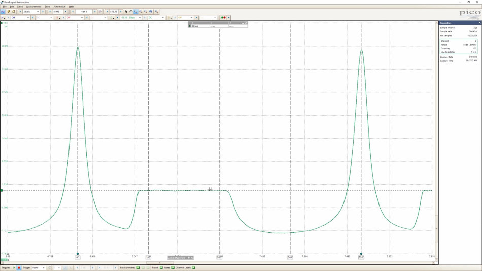
During the in-cylinder capture (Figure 10), I started with a clear flood mode (WOT) followed by releasing the accelerator pedal, throttle body uncapped, of course. This way I can have a cranking and running capture all in one go.
Taking a look at my cranking capture (Figure 11), something really stands out to me. Remember that the throttle blade is wide open and uncapped. I've got 22 inches of Mercury during its intake stroke!
Psia*2 = inHg
11 psia*2 = 22 inHg
There are two things that are true about WOT cranking compression waveforms:
1) Engine rotation is simply not fast enough to cause a vacuum as deep as a running engine will.
2) With a wide-open throttle blade, there is no air restriction in place to even allow for any vacuum to build.
The 22 inches of vacuum during the intake stroke, and it's rounded profile is a result of a descending/ascending piston during inhibited intake valve operation. The result is a peak compression of about 40 psia.
It's safe to say that the exhaust plateau created by the lack of IVO in a cranking waveform, resembles in appearance, the characteristics of that of a running in-cylinder waveform.
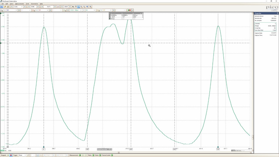
Speaking of which, as you can see in our running waveform (Figure 12), we have a peak compression of about 2 psi, and a clearly defined EVO/EVC (Exhaust Valve Opening/Closing). When EVC occurs, the cylinder is sealed, but the piston is still ascending and the pressure slightly before TDC-E surpasses the pressure at TDC-C, followed by a descending piston ATDC-E and a rounded intake pocket. But there is something that really stands out to me, and that is the “dip” to near barometric pressure during the exhaust stroke, where IVO should occur. There’s only one logical conclusion that I can come up with for this “dip”. I can only surmise that during running conditions, the intake valve opens momentarily, ever so slightly.
Now armed with this information, we went ahead and explained to the customer that a valve cover removal to confirm our theory is not only justified but necessary, and that at this point we're expecting to see two things; no intake valve operation, and also good exhaust valve operation (this will become relevant soon).
Upon uncovering the passenger side valve train, and cranking the engine, an inoperative intake valve and an operative exhaust valve is observed. This is important to note due to the fact that this vehicle incorporates an AFM (Active Fuel Management) system, otherwise known as "cylinder deactivation."
Taking a glance (Figure 13) at service information (a CRUCIAL part of our diagnostic process) reveals that there are four cylinders that can be deactivated upon ECM request, using special lifters, oil passages, and four solenoids that are part of the VLOM (Valve Lifter Oil Manifold) assembly. It does so by grounding the command side of the solenoid, consequently energizing it. While energized, the solenoid opens its valve and allows for pressurized engine oil to enter both the intake and exhaust valve lifter bores simultaneously, ergo, deactivating that cylinder. This is a pretty big deal since, depending on the scenario, may very well lead to a misdiagnosis if disregarded.

Figure 13 - provided by ALLDATA
So how can we infer whether the nonexistent compression is a result of a faulty solenoid?
Since cylinder deactivation is achieved WITH pressurized oil, one can simply take that portion out of the equation. If in fact, the issue was a stuck open solenoid, the failing intake valve should become operational when no oil pressure is available. So I proceeded to crank the engine manually with a wrench to the pulley bolt and, to no effect, watched for intake valve operation.
That's one way we can rule out a stuck open solenoid. There is another. Logic. Seeing that the solenoid controls both lifters at the same time (Figure 14), one can gather that if only one lifter was inoperative, more than likely it is not a result of a stuck open AFM solenoid valve.

Figure 14
At this point, I brought my data to the client's attention, merely suggesting the VLOM assembly as a precautionary measure (due to its documented high failure rate) along with the requirement of head removal and lifter/cam lobe inspection (lifter is beneath the head). Both heads, that is, since if one lifter requires replacement, all lifters should be replaced.
Upon approval, the cylinder heads were removed and the suspect lifter (Figures 15 and 16) was removed from the block. Inspecting it, I could not find a single apparent failure, it looked absolutely perfect from the outside. The VLOM assembly replacement suggestion, however, was declined.

Figure 15

Figure 16
The cam lobe (Figure 17) was also inspected and found to be in pristine condition.

Figure 17
The possibility of roller/lobe damage was taken off the table, and I'm left with only one logical conclusion. The lifter would internally collapse under the tension of the valve spring upon IVO.
Which brings me to my reasoning for that “dip” we saw in our running capture (Figure 12). The failing intake valve lifter does in fact collapse, and inhibit valve opening, but has enough resistance to overcome the valve spring tension just enough to open that intake valve momentarily.
The technician can establish confidence in the client/shop interaction.
Pinpointing a failure makes for a much more confident interaction with the client. It's the difference between saying "it's a collapsed lifter" and saying "let's just replace all top end parts." So we confidently requested approval for replacing all lifters and having the heads sent out, to our local machine shop, warrantied. The client didn't bat an eye and approved the repair. Although we did send the heads out to the machine shop, it was not a case of "send them out and done."
New lifters were oil-soaked, and once I received and installed the heads, I decided to confirm the repair, before assembling the rest. Cranking it manually, my number six intake valve was now fully operational, and we were back in business. I reassembled the engine completely and decided to grab a post-repair cranking amperage waveform. A uniform cranking rhythm can be heard, an even cranking amperage waveform(Figure 18) can be observed, and no running misfires can be felt.
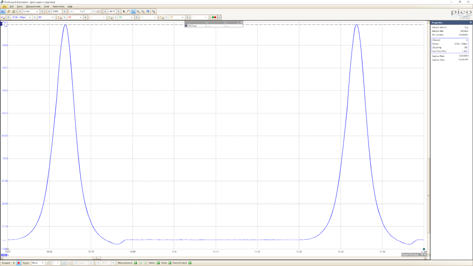
I also captured an in-cylinder cranking waveform (Figure 19).
Notice the exhaust plateau is no longer present and a peak compression of 173 psia is achieved.
I've now justified extinguishing the MIL.
Lastly, I'd like to say that if it were not for in-class training, these techniques would still be oblivious to me. I encourage all not only to go to training but to take advantage of every minute you spend in there. Technology will continue to advance, so should our diagnostic process and client interaction/education.
Although I did my best to include as much information as possible, this case study couldn’t possibly substitute in-class training. It sure can give you an inside look as to what you can expect though!
Thank you for taking the time to read!
David Anderson
April 10 2021
Excellent Case Study. Well done. Great Captures
Andres
September 26 2019
Excellent read, very well explained. Great diagnostic skills !!!
Ian Petersen
August 31 2019
Great bit of detective work by Mario. Well explained and documented too, although I had to read the parts about relative piston positions a couple of times to finally get it!
Larry Pipp
August 28 2019
I have had Roller lifter pitted causing a misfire at Idle. It bounces the Valve. GM late model engines.
karel
August 26 2019
Super cool case! Thanks for sharing and i learned from it. But I have a question. You say, from picture “9” you suggested intake valve not opening. But, what if you had a damaged piston… I know, than you should expect something from suction.. but still, how did you isolate that? With the cylinder wash test?
Mark Stammers
August 26 2019
That’s a great post Mario. Very comprehensive and a really good use of pressure analysis. I always find pressure analysis challenging. Thanks for taking the time.
Brian Good
August 26 2019
Excellent article Mario. Very well written and explained.
JIM MORTON
August 25 2019
GREAT Example of the Diagnostic Power of the Picoscope along with the working knowledge of the combustion chamber. THUMBS UP
David Paterson
August 25 2019
Superb! Logically performed testing; clearly explained; beautifully presented.
This type of testing really is a game changer. Training and the right equipment make that possible. That was a riveting read. Thanks!