PicoScope 7 Automotive
Available for Windows, Mac, and Linux, the next evolution of our diagnostic scope software is now available.
Automotive guided tests
Library of examples on how to perform tests when using PicoScope.

Training
Our collection of training videos, articles, guides and information on training courses.

Waveform library
The Waveform Library is a global database of waveforms uploaded by PicoScope users.

Case studies
Real-life case studies show how the professionals use PicoScope to diagnose vehicle faults.

A to Z of PicoScope
Detailed description of various PicoScope software and hardware features.

Videos
Training resources and demonstrations on PicoScope and the Automotive Diagnostics Kit.

Newsletter
Archive of our monthly Automotive Newsletters.

Documentation
Download manuals, brochures, posters, and training materials.

Reviews and awards
Accolades for the preferred diagnostic tool for service centers and vehicle manufacturers.

| Vehicle details: | Renault Kangoo |
| Engine code: | 5AM 400 |
| Year: | 2014 |
| Symptom: | Poor charging |
| Author: | Ben Martins |
With the growing number of EV vehicles on the road, it is tough keeping up with new technology. The increase of EVs has led to a number of the typical internal combustion engine issues being eliminated, with some manufacturers stating servicing is optional. All that aside, EVs are not without faults. In our previous case study, Steve took us through how important the 12V system is to an electrified vehicle. This time around, we will take a look at a Renault Kangoo with a charging issue and the hurdles that diagnosing this type of fault brings.
Before we start, we have to talk about safe working with EVs, particularly when discussing charging issues:
Firstly, please do not use this case study as a training or instructional guide for working on these vehicles - it is only intended to provide information and give you an idea of possible applications of Pico Automotive products.
Secondly, the required CAT ratings of any measurement tools and accessories you use to diagnose faults on a charging EV depend on the part of the mains distribution network to which the vehicle's charging station is connected (because the possible exposure to transient voltages or short circuit currents changes within the mains distribution network). This is irrespective of whether you are testing the high voltage (HV) or, say, the 12 V system on the vehicle.
Generally, an EV charging station is connected to the mains network after the main distribution board/circuit-breaker/junction box (i.e. on their outlet) in a building. Therefore, your test equipment should have a CAT rating of III or IV when testing an EV connected to such a charging station. However, if the EV charging station is connected to the mains network before the main distribution board/circuit-breaker/junction box, your equipment must have a CAT rating of IV.
Without knowing (via proper investigation) exactly how a charging station is connected to the mains network, you should use only CAT IV rated equipment when carrying out measurements on a vehicle connected to a charger.
In this case study, we know that the vehicle's charging station is connected to the mains network after the distribution board. Therefore, we know we can safely use our CAT III rated differential probe (and connectors) to carry out all our 12 V system measurements (not just HV measurements).
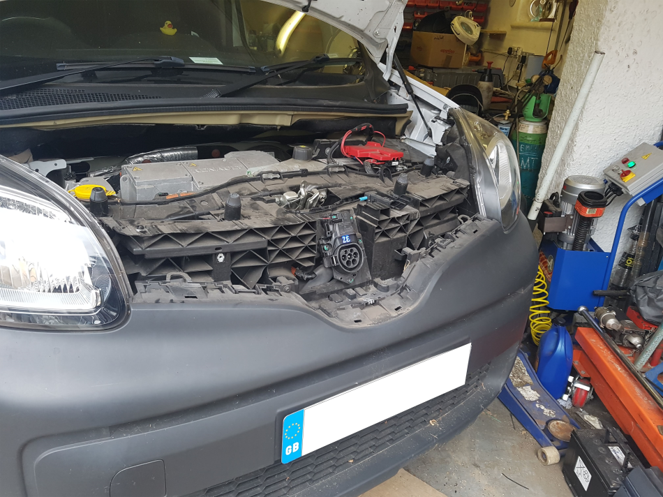
Renault, along with Nissan, is certainly one OEM that has been around the longest when it comes to full battery electric vehicles (BEV) here in the UK. And as they age, the faults start to appear. This 2014 Renault Kangoo ZE was a full BEV, with the battery located underneath the vehicle's floor pan. Charging was done with an electric vehicle supply equipment (EVSE) and the connection was made using the type 2 connector. The vehicle charging inlet was behind the badge on the front grill. This was the 400 version of the 5AM engine, which meant that this Kangoo did not support rapid charging. That, in turn, meant that everything was done through the on-board charger. Unfortunately, this meant charging wasn’t exactly fast, with typical charge times of 11 hours from a flat battery to fully charged on a 3kW home supply. The customer complaint in our case, though, was that the vehicle didn’t charge at all.
As always, we did a quick interview with the customer to get a better idea of the issue and to make sure that we could confirm the fault. The customer was unsure when the fault initially started, as they were still connecting the vehicle overnight. Due to short journeys and a very slow charge time, it only became obvious when the battery continued to deplete. The vehicle had already been through a number of hands, with the last one reporting that due to a dead rat on the undertray there could be rodent damage and that the OBC and inverter needed to be replaced.
Rats don’t bother me, but they’re not exactly nice to find when you’ve got your head stuck under the bonnet! Needless to say, a visual inspection was done first, to ensure that we were free from rodents and any potential health hazards and more importantly if there were any exposed HV cables. All was OK and the next step in the diagnosis was to confirm the fault. We used the customer’s supplied home charging cable connected to a mains socket and switched it on. The indicators on the EVSE all illuminated as expected and no fault was reported. When connecting to the vehicle, the latch engaged indicating the vehicle detected a charging cable. The indicator on the dash also verified this.

Typically, when you connect an EVSE to a vehicle, you will hear the contactors ‘click’, connecting the HV battery to the on-board charger and allowing the battery to charge. In some cases, you will also hear the fans or cooling system starting when charging has begun. When connecting to the Kangoo, however, we heard nothing. We disconnected the charging cable and moved to DTCs.
Next on the list was checking for any fault codes. The only warnings on the instrument cluster were for low battery. The fault codes we found were relating to the low HV battery as expected, but we found nothing else to give any type of direction. Looking at the live data we confirmed that the SOC of the HV battery was at 3%, which was backed up by the vehicle's sound and visual warnings when we turned the ignition on.

As you can see from the image, 3% means that the immobilisation threshold is imminent. This is a dangerous level to be at for an HV battery, as it will reach a point when even charging could not take place when connected to an EVSE. If it were to drop much lower, the battery would have to be removed to be charged with an HV battery recovery system. There are tools we can use if an HV battery has completely discharged and will no longer put the vehicle into the ready mode, but it is better for everyone if you can prevent getting to that stage!
To better understand what happens when we connect a charger to a vehicle, we need to understand what the expected behaviour should be. Typically, most EVs will follow the SAE J1772 standard, which is used by both the vehicle and the EVSE to communicate and signal their status before the charging starts. This can also be found in the later IEC 61851 standard. Some fall outside of this, with the CHAdeMO and Tesla specific connectors operating slightly different. The Type 2 version communicates with the vehicle using a PWM signal and a series of resistors and transistors that control the electrical path. As I mentioned at the beginning, this isn’t a training substitute. I would advise anyone to get their certification to work on Hybrid and Electric vehicles. Here in the UK, there are a few options with the IMI route being the most popular. ZF also offers a High Voltage Expert route through their Technical Training program. To keep it very brief, the EVSE and the vehicle communicate using the PP and CP circuits. On the Type 2 connectors, the PP is there to inform the vehicle that a connector is present and the maximum current the connector can deliver. The EVSE may be able to physically deliver more but the vehicle will only take the current the connector is rated for to prevent overheating.
The CP circuit defines the different stages the vehicle is at during connection. With no connection to the vehicle, there should be a constant +12 V signal from the CP terminal until connected to the vehicle inlet. Upon connection, due to several resistors, this pulls the +12 V down to approximately 9 V. This informs the EVSE that connection to the vehicle has been made and that it now delivers a 1 kHz, ±12 V PWM signal. This PWM is important, as the duty determines the amount of current that is available to the vehicle, which is still capped by the connector rating. Once the vehicle is happy that all the conditions are met, it will switch to another resistor. This pulls the +9V signal down to approximately +6 V to commence charging. There are other voltage levels that it could change to depending on the functionality of the vehicle, such as venting the battery pack, but the important ones are +9 V and +6 V.

While taking all the necessary steps to ensure safety for myself and the equipment, I used the active differential probe to connect to the CP circuit at the on-board charger (OBC). I removed the key from the vehicle to make sure that the connections were as the customer had described and connected the charging connector to the vehicle inlet.

From the capture above, we can see where the vehicle detected an EVSE and we can see the 1 kHz signal start. This along with the latching of the connector tells us that the PP circuit must be OK. As the PP terminal is the first to make the connection, if there was anything wrong here, we wouldn’t see the PWM signal. You might question why the waveform shows +9 V and +6 V but still shows a -12 V? The EVSE generates a ±12 V square wave which is sent along the CP circuit. Inside the OBC we have a diode that will block the negative part, but as we are connected on the outside of the OBC, the scope will see both the positive and negative parts of the signal.
We kept the capture running and expected the voltage level of the PWM signal to drop, which would mean the vehicle had accepted the connector and closed the contactors on the HV battery to allow the OBC to charge the battery. However, we never saw this change. What could prevent the contactors from closing? The signalling between the EVSE and the vehicle appeared to be good, so all that was really left was the communication between the OBC and the Battery Management System (BMS). The vehicle drove to the workshop without any warning lights, so drivability is fine. It was just the charging that was an issue.
The next part was down to more luck than judgement, but it’s nice to have some luck on your side from time to time! I reconnected the scan tool to double-check for any change with DTCs and doing so involved switching the ignition on. However, I had forgotten that I had left the EVSE connected. Not good practise, I know. However, we then noticed that the EVSE clicked and the pattern from the CP dropped to the next step. I’m confident this isn’t expected behaviour, but it makes sense. Putting the vehicle into ready mode closes the contactors. Removing the EVSE and then switching the ignition to ON before reconnecting the EVSE gave us the pattern we were expecting.

At this point, we added a current clamp to verify that current was indeed flowing.

As expected, with the ignition kept on and the charger connected, we could visually see that there was current flowing from the mains to the OBC. After leaving it connected for a while, the battery SOC went up from 3% to 12%, where the audible warning was no longer repeating and the range had increased. We informed the customer of where the testing had taken us and that it seemed to be a communication issue between the OBC and BMS, leading to the contactors remaining open when a charger was connected.
I needed further testing before I could be completely satisfied, but as customers sometimes do, they decided to take the information we had collected back to another garage where they then replaced the OBC. We accept that this could well have been the problem part, but no further diagnosis was carried out before they replaced the part. If there are further tests that could be carried out, why wouldn’t you do them so that you have peace of mind before you start replacing parts that may not fix the fault?
The OBC in this case didn’t fix the issue. One thing that none of us took into consideration was the battery lease program some manufacturers have in place. While I knew about these programs, I had never worked on a vehicle with one and we should all be very aware of this when diagnosing EVs! What I did not know, was that if the lease for the battery is not paid the manufacturer can remotely disable the HV battery from charging, which is precisely what had happened to this vehicle. The current owner wasn’t the original owner and when they purchased the vehicle, that tiny piece of information regarding the battery lease was not fully explained. This resulted in Renault remotely disabling the battery from charging with no warning given to the current owner. What I find strange, though, is there wasn’t any indication from the vehicle, or the serial data, to inform you that the battery had been disabled. From an aftermarket workshop view, if you had one of these turn up and were unaware that the batteries could be remotely disabled, it could cost you an awful lot of time and money.
As I mentioned at the beginning, please don’t use this as a training guide. I’ve purposely missed out connection drawings and some technical information with the hope that those wanting to diagnose these vehicles get the correct and approved training to do so. Hopefully, though, this helps explain some of the new hurdles we have to face when working on electric vehicles. I also hope it inspires a new desire to learn more about how this new technology will affect our workshops in the future. I wish to thank Daniel Mayo for allowing me to help out with this challenge and Peter Melville at HEVRA, for his continued technical support.
Bashar Alqasim
October 01 2020
Thank you very much Ben for this brilliant presentation. Now I can distinguish two types of Technicians; those who read the Pico case studies and those who do not. Two questions please:
1) How the charging can be remotely disabled if the vehicle (of that age) is not telematically connected? Is there any count down timer in that system?
2) How a set up of EVSE connected with the ignition on can “by pass” the stop charging action?
Mark Laimore
September 30 2020
Thanks for that really informative case study. Most people are completely unaware of the hidden complexities of this business…it goes far beyond the technical aspects. Cheers!


