PicoScope 7 Automotive
Available for Windows, Mac, and Linux, the next evolution of our diagnostic scope software is now available.
Automotive guided tests
Library of examples on how to perform tests when using PicoScope.

Training
Our collection of training videos, articles, guides and information on training courses.

Waveform library
The Waveform Library is a global database of waveforms uploaded by PicoScope users.

Case studies
Real-life case studies show how the professionals use PicoScope to diagnose vehicle faults.

A to Z of PicoScope
Detailed description of various PicoScope software and hardware features.

Videos
Training resources and demonstrations on PicoScope and the Automotive Diagnostics Kit.

Newsletter
Archive of our monthly Automotive Newsletters.

Documentation
Download manuals, brochures, posters, and training materials.

Reviews and awards
Accolades for the preferred diagnostic tool for service centers and vehicle manufacturers.

| Vehicle details: | BMW 120 M Sport (E87) |
| Engine code: | N47 |
| Year: | 2006 |
| Symptom: | ABS fault |
| Author: | Steve Smith |
Driving at low speed the vehicle appears to judder, with a yellow warning light illuminated within the instrument panel. The symptom was evident on every drive regardless of temperature and road condition, and had been evident for over a week.
The customer’s description of the symptoms was correct and certainly evident during the test drive. The fault proved to be with the traction control operating at low road speed (the yellow warning light reported by the customer was the traction control indicator).
An extended road test at higher speed confirmed that the juddering stopped, but an additional “DTC” warning illuminated within the instrument panel.
The customer interview confirmed that the vehicle had full service history, no additional accessories installed and no recent repairs. The customer complaint was verified and the vehicle’s identification and specification were confirmed.
The basic inspection confirmed visible ABS connections to be secure and the wheel and tire combination to be the correct specification for the vehicle. Tire wear, brand, orientation, condition and pressure were also inspected and confirmed to be correct. This is an overlooked fundamental inspection when diagnosing ABS and traction control faults. The ABS controller monitors the rate of acceleration and deceleration of wheel speed signals to determine if brake pressure intervention is required. Wheel speed signals vary depending upon tire circumference, and in scenarios where tire tread depths, styles and manufacturer differ, there is potential for tire circumferences to vary by 15 mm or more, resulting in differing wheel speeds during straight-line driving. Such a variation in wheel speed signals will have an adverse effect on brake control intervention.
In a perfect world all installed tires should be the same make and specification (and within the same construction date [stamped on the tire wall]) but in reality this is near impossible. We can, however, physically measure tire circumference and tread depths to confirm whether the deviation between tires is within manufacturer specification and eliminate these variables from our diagnosis.
A vehicle scan confirmed ABS fault codes, indicating signal plausibility and a possible concern surrounding the condition of the sensor pick-up (see code 5DC2 below “increment gear”):

Available service data confirmed no outstanding known issues relevant to wheel speed sensors or circuits.
A road test was carried out whilst monitoring live data from both rear wheel speed sensors via the OBD (On-board Diagnostic) connector. The image below confirms sporadic output from the right rear wheel speed sensor in comparison to the left rear wheel speed sensor.

We referred to the description and operation data from ALLDATA® for in-depth knowledge of component functions. This knowledge is imperative when diagnosing any system and highlights the need for continual research and training.
Possible causes based on symptoms and evaluations made above:
The action plan is based on initial evaluation, experience and accessibility, hence the raw speed signal from the right rear wheel speed sensor had to be measured for integrity using PicoScope.
So far all the information to base our diagnoses on has been obtained via our scan tool, which in turn displays data interpreted and surrendered by the ABS control unit. This introduces a number of variables in the interpretation of data with no verification.
The ABS control unit collects speed signal information, interprets there is an error with the signal and then transmits the error to the scan tool. The scan tool introduces further variables based upon system compatibility and update speeds.
Based on the action plan, we connected the PicoScope kit in order to monitor the speed signal from the right rear wheel speed sensor in real time.
The wheel speed sensors fitted to this vehicle fall under the active design, presenting a measurement challenge to technicians, given their output varies from as little as 6 mA up to 15 mA approximately. With such a low output, the test procedure for these sensors ideally requires the use of a milliamp clamp.
Unfortunately, a milliamp clamp is very expensive (over £400), and given the resolution required at such low output it is unlikely a return on investment would be seen for some time given the minimal use of such clamps. All is not lost though, as there are numerous alternatives with which to measure these wheel speed signals.
Using either the Pico Technology TA018 20 A / 60 A (low amps) current clamp (or better still the Pico TA234 30 A [low amps] current clamp), in conjunction with a current multiplier and relevant Pico breakout lead, we can measure these low currents.
Using Pico breakout leads we extend the right rear wheel speed sensor wires and wind the signal wire through the jaws of the current clamp ten times, amplifying the speed signal by a factor of ten. The amplified current levels that will now passing through the jaws of our clamp will now fall within the 60 mA to 150 mA range, and be easily detected.
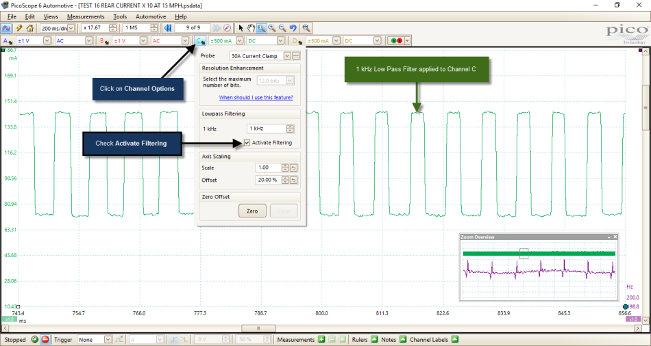
Using the filtering feature of the PicoScope software we are able to detect and measure the switching current of the wheel speed sensor with either of the above current clamps. Activating Lowpass Filtering under the Channel Options button of the channel we wish to filter (checking the box adjacent to Activate Filtering) applied a 1 kHz lowpass filter by default to our selected channel. This setting tells the software to reject all frequencies above 1 kHz and only display lower frequencies (this technique removes unwanted noise from the captured data).
For more information on filtering options, the following tutorial will help with the application of a variety of filters within PicoScope: https://www.picoauto.com/library/training/filtering.
The image below demonstrates the principle of a current multiplier where 5 mA is fed through a coil passing through the jaws of a current clamp 10 times.
The measured current is therefore 5 mA X 10 = 50 mA.

The current multiplier can be seen below applied to the right Rear Wheel Speed Sensor using the relevant breakout leads and TA234 (low amps) current clamp.


The following PicoScope capture highlights two options when measuring active wheel speed sensors. Utilizing either the AC coupling feature to reject the DC voltage present on the signal wire (only display AC ripple), or a Pico (low amps) current clamp.
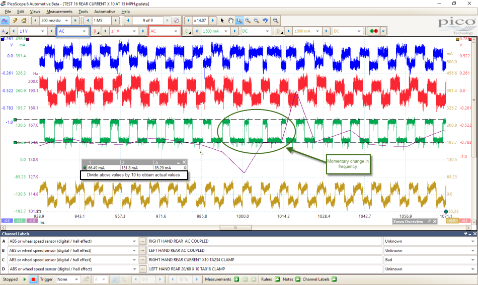
Above, both Channel A and Channel B indicate an output from both rear wheel speed sensors (AC voltage,) but the stability of the signal presents further challenges when looking for anomalies, such as those highlighted by Channel C, connected to right rear wheel speed sensor (see below).
Channels C and D were connected to the right and left rear wheel speed sensor signal wires respectively, using x10 current multipliers as described earlier in this case study. Channel C used the TA234 low amps clamp, and Channel D used the TA018 low amps current clamp.
Channel C confirms a stable output switching from 66 mA to 151 mA (remember to divide this value by 10 ([6 mA -15 mA]), accompanied by a momentary drop in the frequency of the speed signal. This discovery supports the reported fault code and live data acquired from the ABS control unit via the scan tool, and instantly verifies the data obtained.
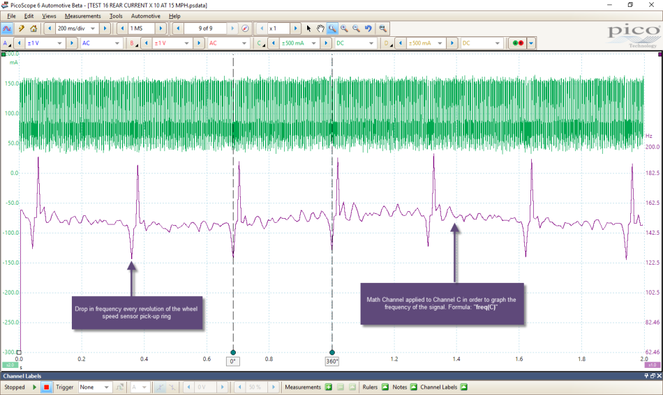
The drop in frequency is difficult to interpret without close analysis of the Channel C waveform using the zoom function in PicoScope. However, using a maths channel (magenta channel above) to graph the frequency, we can easily identify a repetitive drop in frequency on every revolution of the wheel speed sensor pick-up ring (for more information, see creating a math channel below).
Channel D (TA018) also confirms a stable output from the left rear wheel speed sensor; however, the resolution is limited in comparison to Channel C (TA234). Here we can conclude that very low current measurement with the TA018, while possible, is challenging where resolution is essential when searching for anomalies like those identified with the TA234 on Channel C.
For differences between the TA234 and TA018, see PicoChris’ post (#4) on the Pico automotive forum: https://www.picoauto.com/support/post40321.html#p40321
The frequency math channel was created as follows:
Tools > Math Channel > Create > Next > Advanced > freq, with “C” entered between the brackets to complete the formula “freq(C)”. After choosing a colour (magenta) and a scale for our math channel, we completed the set-up and checked the box adjacent to our new math channel “freq(C)”.
So the question now has to be what is causing the momentary drop in frequency every revolution of the pick-up ring? The right rear wheel speed sensor has to be functioning to produce a speed signal, and so the sensor was removed for inspection of the pick-up ring. Examination of the wheel speed sensor tip revealed signs of contact between the sensor and pick-up ring pressed onto the driveshaft.
Rotating the driveshaft through 360° highlighted the point of contact thanks to a bright witness mark. The point of contact results in zero airgap between the sensor tip and pick-up ring, hence a drop in frequency of the speed signal. The driveshaft was then removed for closer inspection, revealing ovality of the pick-up due to the effects of corrosion about the outer driveshaft joint.


The following video demonstrates the degree of runout (1.70 mm) of the pick-up ring as a direct result of swelling due to corrosion of the driveshaft joint:
Rear right driveshaft accompanied with right rear wheel speed sensor.
Replacement of the above components confirmed a successful repair with fault codes erased, stable driving at low speed (no juddering) and no illumination of warning lights as seen during the videos included in the Description section above.
I think it is safe to conclude that Pico current clamps remain essential accessories to any diagnostic tool set. When combined with the PicoScope hardware and software, this case study demonstrates the further potential of what is often overlooked as a tool of choice during diagnosis.
Without the relevant current clamp, how could we verify the scan tool data recovered in the diagnosis section above?
By its nature, the current clamp has to be the most non-intrusive diagnostic tool capable of capturing events not seen when measuring voltage, whilst secretly confirming voltage, ground and component to be functioning correctly based on Ohm’s law.
You could argue that if current flow is correct, then voltage, ground and component are functioning normally, so saving you two precious scope channels for other measurements!
A big thank you to Kevin at Ives Garage for his assistance throughout the diagnosis and repair of the vehicle.
https://www.picoauto.com/library/case-studies/1961-jaguar-e-type-3-8-unstable-idle-speed
https://www.picoauto.com/library/case-studies/2007-toyota-hilux-2-5-tdi-p0340-p0335
Leonardo
December 15 2019
Muito bacana os diagnosticos !
Hophy
February 09 2017
Hi, i just have a question, why don’t just use the voltage to test the wheel speed.
Barrie Broomhall
July 04 2016
Hello all from Australia,I have just finished reading an article on misfiring, lack of power on a Jag 6 cyl E type,as one person described I too used a “monster” scope and rolling road,for 30 years,updating the Sun Scopes as the years went.
Most praised the diagnosis which was fixed by fitting, I imagine Lumenition or such.
However I agree - with another poster that IMO wouldn’t have been the problem,if an experienced mech from those days were available ,he would have pointed out that the primary current does’nt earth thru the baseplate pivot,from an electrical design point of view that’s a chancy earth at best,there were small braided earth wires in Lucas distributors some from the points plate to the fixed plate - bur in Jags the lead went from the points plate to the distributor cap indexing slot in the distributor outer body case,there held down by a 2-3BA? Phillips headed screw.Which were often loose!
These loose -or fractured inside the braiding, causing a spark scatter easily seen on the primary pattern. Every Lucas distributor I found the screws were tightened or checked,I had one car come in that the owner had been chasing a misfire for 4 years,and spent a LOT of money too!LOOSE SCREW!
I have a poverty model Pico that in my dotage,I “play” with,there is no doubt that any mech that aspires to do decent and meaningful diagnosis should have a scope - or just concentrate on brake relines, suspension bushes etc,Regards Baz


