PicoScope 7 Automotive
Available for Windows, Mac, and Linux, the next evolution of our diagnostic scope software is now available.
Automotive guided tests
Library of examples on how to perform tests when using PicoScope.

Training
Our collection of training videos, articles, guides and information on training courses.

Waveform library
The Waveform Library is a global database of waveforms uploaded by PicoScope users.

Case studies
Real-life case studies show how the professionals use PicoScope to diagnose vehicle faults.

A to Z of PicoScope
Detailed description of various PicoScope software and hardware features.

Videos
Training resources and demonstrations on PicoScope and the Automotive Diagnostics Kit.

Newsletter
Archive of our monthly Automotive Newsletters.

Documentation
Download manuals, brochures, posters, and training materials.

Reviews and awards
Accolades for the preferred diagnostic tool for service centers and vehicle manufacturers.

| Vehicle details: | Fiat Kobelco E135 |
| Engine code: | Iveco |
| Symptom: | Engine stalling, Power loss |
| Author: | Ben Martins / Mike Valentine |
After the release of our Engine and Hydraulics kit, it seemed apt that I was asked how the kit can be applied to a faulty machine. What we have here is a Fiat Kobelco E135 tracked Excavator, fitted with an Iveco 4-cylinder diesel engine. There is nothing too fancy about the engine: it is an old-type geared industrial engine with a rotary pump and mechanical injectors. In terms of engine electrical equipment, there really isn’t much going on!
Something I’ve learnt is the access to technical information is very limited for plant machinery. You can purchase individual manuals but there is no central hub or datacenter for Plant machinery, which makes looking up anything about this particular machine rather tricky!
As always (but particularly in this case) the customer interview was vitally important. According to the operator, the machine had always been a little temperamental, but it really started acting up four months ago. The engine would stop suddenly, while the machine was being operated!
The trouble with hydraulics is if the prime mover stops for any reason then everything stops. For example if you are tracking across a site entrance and it cuts out halfway, there are only two choices: it starts again or it is pushed or dragged out the way. The machine was visited on a number of occasions by a mobile technician who traced the fault to a stop solenoid but also found some metal fragments in the high pressure pump. This was then sent away for an overhaul with the belief this was the cause of the problem with the stop solenoid. The stop solenoid failure would make sense due to limited electrical components on the vehicle and the fact there is no warning signs of anything playing up. A stop solenoid would definitely cause the symptoms the customer has been complaining of.
Solenoid changed and machine back to work but 4 weeks later the same thing happens again, engine cuts out all of sudden with no warning. After some more investigation work turns out the stop solenoid had failed again. Another one fitted and back up and running. Three to four weeks pass again and the same thing. In total the machine has had four stop solenoids in as many months and has got to a point where the customer is keeping a spare on site to replace the stop solenoid in order to keep the machine working. As far as I am aware stop solenoids are quality parts, plus supply for certain components is limited to OEM only. Due to the lack of information or on-board diagnostics found on plant machinery, I was asked if PicoScope could uncover anything that may be causing this premature failure of the stop solenoid. Whilst I love a challenge I wasn’t quite prepared for some of the difficulties I was going to encounter.
As I mentioned early the lack of information was quite surprising considering the plant industry is as big as it is. What I’ve also learnt is working on these machines is difficult to say the least. I guess the reasoning behind using older style rotary fuel pump and timing gears is because once the engine is installed, you really can’t get anywhere near it!! I had a letter box style gap to attempt to access the engine bay or the alternative was to go in from above. Either way this was not going to be easy.
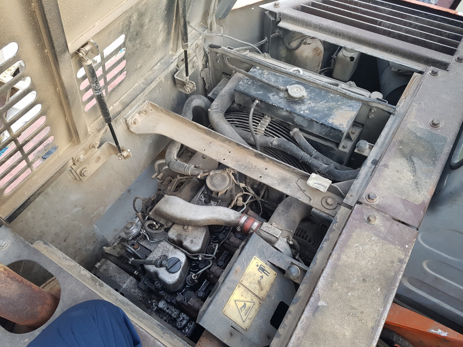
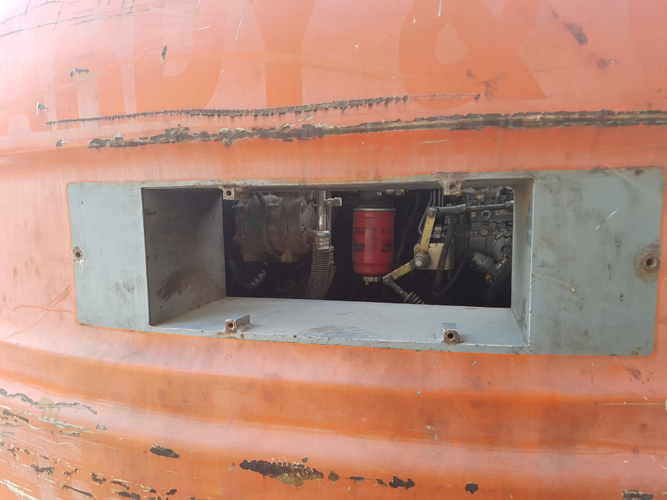
Luckily in this instance the fuel pump is almost directly in line with the letter box which meant access to the stop solenoid was relatively straightforward. Also worth a mention here is the extra-long leads that are supplied with the Hydraulics kit. These became really handy on a machine of this size and I think those working in this sector would benefit from the extra maneuverability they give.
In order to assess what is going on with the machine I felt best to be as non-intrusive as possible due to the limited amount of information available. For this reason I started with a simple current measurement on the stop solenoid, and the battery voltage going from Key Off to Key On. All I wanted to see at this point was there was a change within the current for the stop solenoid to prove it was working.

From this I can be confident that current is flowing through the coil in the stop solenoid, and therefore will at least get the engine to start! So, time to start up.
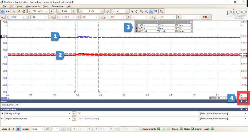
One thing that stood out to me when starting the engine was a sporadic rise in battery voltage which was also seen in the current at the stop solenoid. Applying some scaling to the current meant this increase could be seen easier. The increase in battery voltage and current is seen in the electrical system and in this instance the voltage rises to just over 30 V. Looking at what could increase battery voltage on this particular machine, the only thing that has the ability to do this is the alternator.
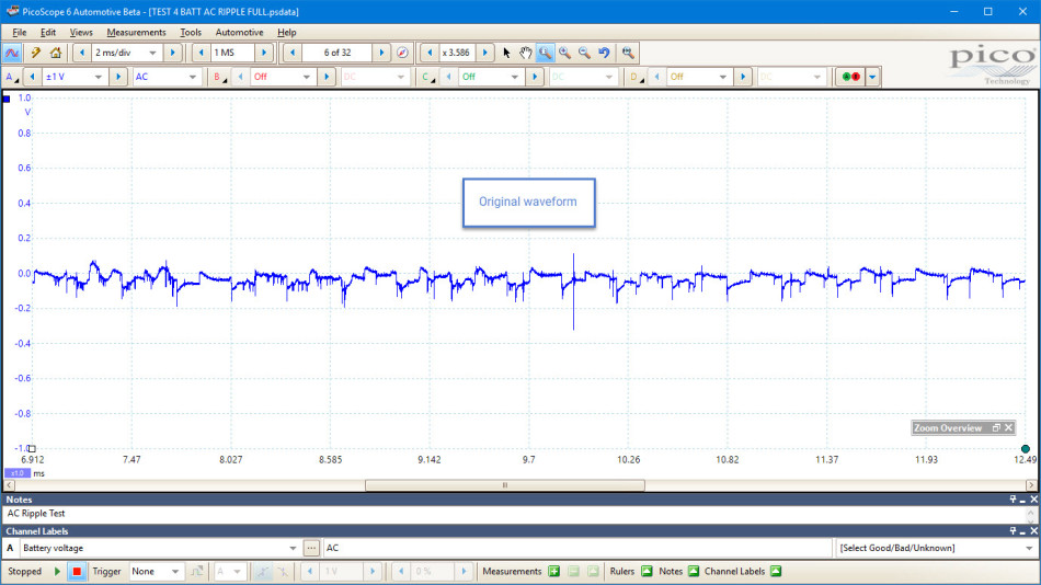
With this in mind I felt it necessary to look at the battery voltage AC coupled and observe the alternator ripple for anything out of the ordinary. I also made use of the fact I have the option for four channels (when space is limited gaining as much information as possible in one go can be extremely helpful). I now have battery voltage AC /DC coupled, stop solenoid current and voltage connections. This will give an idea of what is happening at the stop solenoid when there is a slight increase in battery voltage. What I found was extremely interesting and something I’ve not seen before.

The great thing about looking at battery voltage AC coupled is we can see the ripple from the alternator in much greater detail. This provided me the information to determine things such as diode failure and voltage regulator faults. We can clearly see that there is something considerably wrong with the ripple from the alternator. It would appear that for around a second the voltage is almost completely unrectified and we see a sine wave typically associated with AC voltage. We would normally expect the AC ripple to hover around 0 volts but with a ripple effect that might swing from positive to negative, but never exceed 1 V. From the above capture we are set to ±1 V which when this wave occurs actually over-ranges. We also see a lot of sporadic spiking within the ripple as well which is also seen in the rest of the electrical system. When we see this swing in the ripple we also see an increase in the DC voltage of the system which can be seen at the stop solenoid and also in the current. Knowing that this behavior is not to be expected from the alternator it was strongly advised to get the alternator replaced, but what about the customer’s original complaint with the stop solenoid failing over a period of time? Could this overvoltage cause the solenoid to fail? Well, yes it can. Excessive voltage causes excessive coil current which overheats the coil within the solenoid and therefore burnout. There is both an increase in voltage and current when the AC ripple output changes, which would back this theory up, but would this be enough to burn the coil out? I wasn’t able to prove conclusively that the AC ripple was the cause of the failing stop solenoids as typically while I was with the machine it didn’t cut out. What would have been nice was to have seen the battery voltage increase to a point where the current at the stop solenoid was great enough to overheat the coil and burn it out but as always time was against us and the customer required an answer.
With this in mind the one thing we are confident of is the alternator signal is not correct and the alternator itself requires replacing before any further checks could be carried out. The customer agreed and once the repairs had been completed I returned to the machine to take the same readings I had with the old alternator. The results speak for themselves.

We can see that the sporadic spikes have now gone and apart from a little noise which could be down to a number of things, the signal is a lot clearer. Having left the engine running for a period of time, there were no signs of the ‘wave’ I was seeing on the original alternator and the voltage was stable at 28 V.
The machine has now been running for over a month with no reported issues thanks to continued feedback from the operator. I guess with anything intermittent it would be great to capture the exact moment when the fault occurs, but sometimes proving what it isn’t is just as important as proving what it is. I think what I have learnt here is that despite the lack of information, despite not being able to see most of the components , and no access to DTCs, sometimes starting at the very basic of tests can help give you some direction and understanding. In this case it was purely looking at battery voltage.
Ben Martins
February 26 2018
Hello Andy,
Thank you for raising your questions and I will try to answer them as best as possible. With regard to the 5V oscillation, honestly, I don’t know. It could be down to a number of things and as you’ve pointed out, all after the solenoid has been turned on. The lack of technical information really does hinder the diagnostic approach in this case and not having a wiring diagram to utilise again makes things very difficult to analyse in any real depth. It could also be there are number of solenoids that are activated on the hydraulic side of things in preparation for engine start. Some hydraulic pumps will allow the engine to start up under no load conditions and so will activate the position of the swash plate to prevent this. I’m not saying that this is the case for this particular machine but it is something to consider during an ignition on event.
You are correct that the second image the engine is started and running and I can see your point about current dropping once the engine has started. It could be that there is a higher resistance or it could be that the solenoid doesn’t need as much current to hold it open. This is a purely a theory in my head and I’m not disregarding the possibility of a volt drop due to the vast amount of metal work, the cables and the age of the vehicle but what if the pump drawing the fuel will help to overcome some of the spring force of the stop solenoid. If there is a fluid flow through an orifice then a thought would be some of this ‘work’ will be exerted on the stop solenoid and therefore less current will be required to hold the solenoid in the off position. As I said I do need to prove this and it is just a thought in my head but trying to find some of these older type engines can be a little tricky in a world of Common Rail! As I said a voltage drop certainly isn’t something to disregard but before I was asked to take a look the previous stop solenoids were checked which all had open circuits after the machine had stopped. If there was a lack of voltage to hold it open then the coil windings would still be intact.
We really do appreciate all the feedback from the case studies and often we discover new techniques and new ways of looking at the data we see in the vehicles we face.
Kind regards
Ben
Ben Martins
February 26 2018
Hi Richard,
Thank you for comments and I’m hoping that I can bring some more 24V systems as you’re right it, isn’t something we see very often and not something I’ve been exposed to for a number of years!
To answer your question on rectification, in theory there shouldn’t be any real difference. The alternator is fundamentally the same in operation. I think I’ll need to carry out some further tests on 24V systems to see if this is the case and if the ripple we see in the captures I acquired are the same. The other issue surrounding this particular machine is the length of the earth from the battery to the engine. There is a lot of heavy metal between the earth points which could lead to some interference and possible alter the signal we would expect to see. Again I will need to get some further captures and have some comparisons to be able to fully answer your question.
You are correct in saying that the output is from the positive aspect. I think it is important to remember that when we AC couple a channel we are removing the DC offset to just show the ripple on top and reference around 0V so whilst it would appear that there the voltage appears negative this isn’t the case. There is a lot of discussion as to whether we need to AC couple at all and as always there are pros and cons to both. The AC signal is always present on the DC and there is an easy way of proving this. If we captured battery voltage using both DC and AC coupling with a vehicle running and apply filtering to both, then if we increase the scaling of the DC channel to say 50 times you will now see the AC ripple on top of the DC signal. This requires a lot of work and when it looks like the snow is about to fall, time was more important to me hence the need for AC coupling.
Sadly I didn’t capture the current output there a number of reasons for this, one being the weather! Hindsight is a wonderful thing and if I could do it again I would have measured current but with these machines the luxury of a nice dry workshop isn’t the case and time was very much against me. Because the fault was as intermittent and unpredictable, I was looking for things that were different and out of the ordinary. When machine showed the fault in rectification there were no additional loads being applied, it wasn’t anywhere close to being at operating temperature but I completely agree with you, a sudden demand for current can cause diode failure. With the lack of additional loads and the inconsistent un-rectified signal I made the call on the alternator. As I mentioned the operator has reported the machine is still working as expected since the alternator has been replaced.
As always we are learning all the time and it is good to see questions being asked.
Kind regards
Ben
Andy Rogerson
February 14 2018
Hi!
there is lots of information in the traces that hasn’t been discussed that make me question the conclusion that was drawn. Some more information would be helpful.
In the first trace, there is a +/- 5V voltage oscillation after the solenoid is actuated. Any suggestions what the cause was? There is another similar but not quite so large voltage dip earlier in the trace too. At this time, solenoid current was 950mA. Of course, the alternator wasn’t’ charging at this time.
It isn’t clear where abouts on the 2nd trace the engine started. I think we can assume it was before the displayed trace started as the battery voltage was higher than the earlier trace. The solenoid steady state current at this time has now reduced to 680mA. this is limited by resistance in the circuit. What is the cause of this increase of resistance? If there is unwanted resistance (and therefore volt-drop) in the circuit, there could be insufficient voltage to reliably operate the solenoid
In the third trace, why the need to use AC coupling, rather than just zoom the voltage scale onto the DC signal? The shape of this waveform is dependent on the high pass filter applied to the DC coupled signal. As you’ve demostrated, the signal is distorted relative to the real voltage (DC coupled). I don’t think we can see any alternator ripple within this waveform, at this timebase. As already mentioned, the positive/negative spike is a function of creating the AC coupled signal. Using a zoomed version of the DC coupled trace is a much more reliable image to interpret. The current remains about 0.7A, so much lower than the original trace.
You’ve talked about excessive current leading to coil burn out, but the current with engine running is much less than with engine off. This then implies low voltage across the solenoid rather than high voltage that you are proposing as a cause. Low voltage across the solenoid coil can of course lead to failure to operate the coil.
Richard Lukins - FioranoCars
February 03 2018
HI Mike and Ben
Another interesting and obscure failure that would be near impossible to find without a scope, and a classic case of symptom verse cause throwing the mobile tech. Well done for identifying the issue.
However, a few questions/comments, especially as I don’t see much 24v 😊
1. On future posts, could you try to scale comparison screen shots to the same settings, it just makes reviewing them easier 😊 (both time base and measurement scales please)
2. The ripple is nothing like the rectification I’m used to seeing on a 12v system (series of 3 almost perfect elliptical crescents to the positive), on either the before or after shots, is this typical of all 24v systems? In terms of both the shape of the signal (almost square rectification), and the lack of being able to identify the 3 phases?
3. The positive element of the AC appears, visually anyway, to be very low, say under 5% duty (on the New waveform), so surely this indicates the amps output would be pretty low too? Don’t we only get DC Current (amps) from the positive element of the post rectification A/C signal? Sorry if I’m missing something elementary, just trying to understand this clearly different system from those I’m used to!?
4. Did you capture amps output from an alternator, if so was there an extra demand being made/output which correlated to the sudden rectification failure? We’ve seen issues relating to amps (from inrush of motors like fans/pumps) putting a sudden load on the alternator and allowing weak/failing diodes to then fall over, so we always test the output amps with DC voltage and A/C ripple to understand better the alternators characteristics and any issues ... a one second fault time could correlate to a “inrush”, and that might identify the true root cause, and show the alternator is failing as a symptom due to a long-term “inrush” issue damaging it? Something to consider should the new alternator fail?!
Thanks for another great example of Pico’s capability
Best Richard
Ian Petersen
February 01 2018
Excellent detective work. A story to keep in mind when working on older supposedly ‘no electronics’ machinery. Even the humble alternator has enough electronic components to cause odd issues if ever the smoke escapes from them…
Stuart Dawson
January 31 2018
Thank you for really great informative review. You are so right about going back to basics, I also always have a tendency to over complicate things, especially with all the different technology we have now… really good example of good thought, basic diagnosis. Thanks!
Martin Rubenstein
January 31 2018
As ever, a thoroughly fascinating read and another interesting lesson in diagnostics and the power of the PicoScope.


