PicoScope 7 Automotive
Available for Windows, Mac, and Linux, the next evolution of our diagnostic scope software is now available.
Automotive guided tests
Library of examples on how to perform tests when using PicoScope.

Training
Our collection of training videos, articles, guides and information on training courses.

Waveform library
The Waveform Library is a global database of waveforms uploaded by PicoScope users.

Case studies
Real-life case studies show how the professionals use PicoScope to diagnose vehicle faults.

A to Z of PicoScope
Detailed description of various PicoScope software and hardware features.

Videos
Training resources and demonstrations on PicoScope and the Automotive Diagnostics Kit.

Newsletter
Archive of our monthly Automotive Newsletters.

Documentation
Download manuals, brochures, posters, and training materials.

Reviews and awards
Accolades for the preferred diagnostic tool for service centers and vehicle manufacturers.

| Vehicle details: | Nissan X-Trail |
| Year: | 2008 |
| Symptom: | Cutting out, P2146, P2149 |
| Author: | Ben Martins |
Something that crops up time and time again is how to test and diagnose piezo injectors without having to send them away. And even when you send them away it’s not always straight forward, with many diesel companies saying they can only really check spray patterns as they can’t load the injectors the way they would be when fitted to the vehicle. I had the opportunity to try out some new testing methods when I was asked to take a look at a Nissan X-Trail with two fault codes that pointed to all four injectors. The fault codes were “P2146: Injector 1 & 2 Power supply short to ground” and “P2146: Injector 3 & 4 Power supply short to ground”.
We needed to confirm the fault to start with. The customer’s descriptions on the job card read: “under load, wants to conk out”. You’ve got to love certain customer’s comments. After a short interview, we had gathered some more information: that the vehicle would start and run from cold just fine. It behaved perfectly until they needed to overtake or put the engine under load, which resulted in a stall. This issue would progressively get worse until it was impossible to start the engine and one would have to wait till it cooled down again before restarting it. Clearing the codes and carrying out a road test confirmed this and I can say that it certainly was worrying to experience the vehicle cutting everything!
Having confirmed the fault, we could now start looking into what was causing it. A step that is often excluded is to check for possible software updates and known issues. Technicians always have to keep an eye on the clock when working with on a diagnostic job so it is better to check this first as it may well save time going forward. I think we can all say that at some point we’ve chased a fault only to find that there was a software update that could have saved us a lot of time and pain.
Currently, we had the two fault codes pointing to four injectors but would you replace them based on the fault codes alone or should we do our best to find the cause of the fault?
While looking for the description of the fault codes we discovered another source where the same fault code meant something different. This is a problem that we frequently have to deal with and the only way to find accurate fault code description is to refer to the manufacturer’s technical information site. Here we find that P2146 is “number 1 and 4 cylinder fuel injector circuit open” and P2149 is “number 2 and 3 cylinder fuel injector open” with the DTC detection description ID for an improper voltage signal sent to the ECM through Cylinders 1 and 2 and Cylinders 3 and 4. This is where using ‘dealer’ level tools may make your life that little bit easier, but I know that for multi-brand workshops this is a considerable commitment and expense that may not be economically possible.
The repair procedure for injector power supply circuit open or short doesn’t exactly fill me with joy either. Checking for wiring continuity is becoming a thing of the past, as we would much rather see how the circuit performs under load. This is often done with a bulb, or we could use the floating input capabilities of the 4225 and 4425 PicoScopes and look at the voltage drop between the two ends of the wire. If you want further information on floating inputs and voltage drop testing, please click this link.
First, I wanted to make sure that the injectors were getting the correct signals from the ECU. Nissan, along with many other manufacturers, uses piezo injectors in its diesel engines. One thing to remember about piezo injectors is that the voltage levels are much higher than on solenoid types, and they can reach 250 V on some systems. If you ever find you are unsure, always use an attenuator and be mindful of the risks involved with high voltage. If possible, always use suitable breakout leads during injector testing. The infinite and more precise control over injection means that stricter emissions standards can be met and that they are easier to control, but these benefits do not come without problems. Piezo stacks are very sensitive and fragile. It doesn’t take much of a shock to damage the stack, and even having them lying down on a workbench for a few days is enough to dry them out which, when refitted and used, can cause unnecessary stress to the stack. We can find further information on these injectors in this Guided Test.
As I had four channels at my disposal, I used three channels to observe the voltage on both sides of the injector as well as the current.

In the screenshot you can see that the injectors were being supplied with 160 V. I used an attenuator to check the voltage, to make sure the ranges were safe to use with the scope alone. You can see why the use of attenuation is so important, as not many other scopes have a high enough input rate to handle this kind of voltage. You can also see that both sides of the injector are exposed to the 160 V but it was only when the ECM provided a ground path for the supply voltage that the current started to flow. It is important to remember that current only flows when there is a voltage differential. Some manufacturers may have a base voltage setting of, say, 5 V for open circuit detection but it is only when there is a voltage differential that the current will start to flow.

By utilising the peak to peak measurement in PicoScope 6, I could see if there were any excessive differences between the other cylinders. From cold, they were all between 15 A and 17 A at idle. Not much to gain from that, so now it was time to see what would happen when the engine cut out.
As I did not know if the fault was associated with a wiring issue, an injector, or all four injectors, I decided to keep it relatively simple to start with. Due to accessibility I decided to look at the injector on Cylinder 3 and captured a camshaft signal to indicate engine running. Off we went to do a road test so we could see what was happening when the engine stalled.

The fault occurred during the road test and we managed to capture it with the PicoScope. When the engine stalled there was no longer a signal being sent to the injector, yet the engine was still rotating which was confirmed by the camshaft sensor output. I took the opportunity to look at the crank sensor output to confirm that the ECM could still see that engine was rotating. Proving what it is not is sometimes just as important as proving what it is. I also had a spare channel here so in an effort to rule out as much as possible I looked at the ECU power supply as well.

Without a crank sensor, the engine would cut. With no codes pointing towards a faulty sensor, it was important to establish what it was doing when the engine cut out. This vehicle had a floating crankshaft sensor (you can find more information about this on this page.
As you can see from the capture, it did not cut out or misbehave prior to the engine stall. Therefore, we can safely rule it out as the fault. You’ll notice that the engine speed math channel I’ve created is indicating a speed increase in RPM after the engine had stalled. The reason for this was that the clutch was being depressed. Just before the engine stalled the vehicle was accelerating and when it stalled, the engine speed decreased quickly. The depressed clutch, however, reduced the load on the engine and so the speed increased momentarily.
You can also see that the ECM supply remained, which means that the injectors cutting out was not down to a decrease or drop in the power supply either. Another item to tick off the list. While the testing continued, the fault did indeed get progressively worse the hotter the engine got, until it got to a point where the engine would no longer start.
A quick recap on what we knew so far:
We had a vehicle that cut out when under load and progressively worsened as the engine temperature increased.
There was no loss of crankshaft position or camshaft position when the fault occurred
We could see that the injector’s voltage supply was cut when the fault occurred.
This led me back to the injectors.
Knowing that current gives an indication of work performed by an injector, and with the engine now stalling consistently, I connected to Cylinders 1, 2 and 3. Cylinder 4 was buried under the intake pipework. The other thing I thought about looking at was the earth connection for the engine. One of the codes was a short to ground so you never know, it might show something.

All three injectors I had connected were drawing current when operating but something stood out here that I hadn’t noticed when the vehicle was cold. The injector on Cylinder 3 had long downward spikes of current during the other injection events, which on the others was barely noticeable if even there. Taking a closer look at the spikes I measured 3.3 A, admittedly not for very long, but could this point me in the right direction?

After taking some time to remove more components, I was able to carry out a resistance test on all four injectors. Cylinders 1, 2 and 4 were all between 179 kΩ – 182 kΩ and Cylinder 3 was measured at 0.8 kΩ. Remember to always refer back to your technical information to see what is regarded as normal range as this can differ from between manufacturers. However, I was confident that this looked like an injector fault. It would have been nice to see what had occurred if I’d taken the resistance readings when the injectors were cold, but as always, time was against us and I didn’t have the option to wait for the engine to cool down. I wonder if the results from cold would have been any different and if resistance measurement is enough for these injectors.
One way to test them further, but that I have never tried, is with an insulation tester. Normally we would be using this tool on hybrid and electric vehicles. However, when you think how a piezo injector operates, a high voltage is applied to a stack of crystals and when current flows it causes them to change shape. This all takes place in a metal casing that is bolted to an engine that ends up connected to battery negative. To keep this voltage inside the injector there will have to be some form of insulation as we don’t want this high voltage to be able to get to the metal casing and find an easier path to ground.
When carrying out insulation testing on an electric vehicle, we apply a voltage or ‘pressure’ to a component and test it to make sure that nothing ‘escapes’. By working along this principle, we should be able to determine the insulation of an injector. We know that the injectors have a supply of 160 V and with insulation testing, we should always be testing at the stated voltage or above. In this case, the 250V range. By using breakout leads, I was able to supply the injector with the voltage while monitoring the body of the injector with the negative side of the tester.
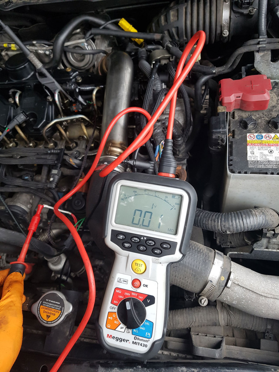
The maximum voltage applied to the injector was only 1 V before the tester recorded a fault and, as shown in the image above, a small measurement of 0.01 mΩ. The other three injectors all managed the full 250V with resistance readings over 5 GΩ. As I was happy that this was indeed the work of one single injector and not all four, I ordered a new one.
To further prove that this was the fault, I reconnected the injectors and brought the vehicle back to the point where it would start and then cut out immediately. With the ignition switched off I disconnected injector 3 and tried to start the engine. It started the first time, even with only three cylinders connected. I reconnected Cylinder 3 to find it cutting out again.
With a new injector fitted and coded, the customer has now got their vehicle back without having to pay for the parts and labour of replacing all four injectors.
Things to discuss
Thinking slightly outside the box: With a 4225 or 4425 scope to hand, we have the option of using floating inputs. Could we potentially see a change in voltage levels if an injector was allowing voltage to pass through to the body of the injector and ultimately back to ground? If so, if we connect the signal part of our test lead to the body of the injector and the ground side to the engine block, would PicoScope detect anything?

The above capture has the injector on Cylinder 3 disconnected and I’ve applied a very heavy filter of 500 Hz to Channel A. This was just to experiment and see if there was anything in the signal that could point us to this type of fault. The rotation rulers help to point out repeating patterns. We can clearly see something happens just before the injector on Cylinder 2 fires. I found this a little odd unless this was due to effects of something else from the engine. I decided, however, to compare it to the capture from when I reconnected the injector for Cylinder 3.

With the injector reconnected and the same 500 Hz filter applied, we can see that the signal on Channel A looks very different. Without the obvious pattern from before, I measured 10 degrees between the injection events for Cylinder 2 from the previous capture and used my rotation rulers in the same place on the capture with all three cylinders connected. Sadly, I could not see anything that linked the injection event to Cylinder 3, which we know is the faulty injector, and fluctuations from connecting our test lead to the injector body. Maybe a better technique, keeping the connections closer together and AC coupling would help reveal more in the future. All food for thought and definitely worth a try if there is time to experiment.
Darren Fraser
August 06 2020
Thank you so much Ben! I’m actually going to be doing a bit of scope work tomorrow on a Landrover TDV6 that we’ve just done the engine on and we are having major drama getting it running. I’m sure this case study will help me immensely.
Marc Laidlaw
March 06 2019
You sir are a wizard. I have just read this and love how you are so methodical in your search for the answer. I have been in the industry for a while now and with all the dealer training courses attended, this level of diagnosis was never taught. With cars getting so complex now and no one teaching the correct ways to detect such issues, its obvious that much of the workshops do not have access to key data and the special tools such as the Pico scope to deal with such problems. Keep up the good work. Regards Marc
Steve Scott
March 03 2019
Awesome case study, thanks for sharing it.
Kim Doerr
March 02 2019
Interesting read Ben, just shows the right way to do it. So many would of replaced all four injectors and fixed it without the satisfaction of knowing why it worked. Well done.!!
Graham Hanslip
February 26 2019
Well done!
Working at this level when under the pressures of a busy business in impressive. A very interesting article
Issam
February 20 2019
Very good job & many thanks for sharing!


