PicoScope 7 Automotive
Available for Windows, Mac, and Linux, the next evolution of our diagnostic scope software is now available.
Automotive guided tests
Library of examples on how to perform tests when using PicoScope.

Training
Our collection of training videos, articles, guides and information on training courses.

Waveform library
The Waveform Library is a global database of waveforms uploaded by PicoScope users.

Case studies
Real-life case studies show how the professionals use PicoScope to diagnose vehicle faults.

A to Z of PicoScope
Detailed description of various PicoScope software and hardware features.

Videos
Training resources and demonstrations on PicoScope and the Automotive Diagnostics Kit.

Newsletter
Archive of our monthly Automotive Newsletters.

Documentation
Download manuals, brochures, posters, and training materials.

Reviews and awards
Accolades for the preferred diagnostic tool for service centers and vehicle manufacturers.

| Vehicle details: | Toyota Camry (import) |
| Engine code: | 2GR-FE 3.5 Litre V6 Quad Cam – Dual VVT-i |
| Year: | 2013 |
| Symptom: | MIL on but no symptoms |
| Author: | Steve Smith |
I am sure many of us have experienced the limitation of only having four PicoScope channels while being deep in the battle of diagnosis. With the PicoScope software, we have the advantage of using reference waveforms to provide additional channels for comparison, so all is not lost. However, the acquisition of reference waveforms requires a robust technique to ensure that the timing correlates with the existing captures, and this has the potential to introduce a variable. Diagnosis commands that all variables are kept to a minimum, and from my perspective, there have been numerous occasions when six channels would have been perfect. The case study below is one such example.
PicoScope is the scope of choice for over 25 different vehicle manufacturers (VMs). As a direct result, we are fortunate enough to provide off-site VM support to a variety of vehicles and technologies where our scope delivers a conclusive diagnosis. Keep reading to see what we found this time around.
The customer reported that the engine warning lights (MIL) illuminated after 2-3 miles of driving with no loss of performance or drivability issues. The fault has been present since purchasing the vehicle approximately 2 months prior. The selling garage has replaced numerous components in an attempt to rectify the fault.
A road test of the vehicle proved no drivability issues and confirmed that the engine warning light was continually illuminated. Cycling the ignition and restarting the engine did not reset the MIL, which suggested that this was a permanent and present fault stored within the PCM.
After verifying the customer’s complaint, we confirmed the Vehicle’s ID and Specification.
The Customer/Garage Interview highlighted a partial service history, a number of accessories installed, and the recent replacement of the following components:
The Basic inspection confirmed that the engine oil level and quality were good, that all visible components were correctly installed, and that the connections/harness routing in the engine bay were secure.
A vehicle scan of all onboard control units revealed the two fault codes listed below:
ENGINE- P0016 Crankshaft Position- Camshaft Position Correlation (Bank 1 Sensor A- Intake)
Main Body-B1245 Lost Communication with Wiper ECU LIN
Before we dive into what could cause these codes, it is paramount that we take a step back and check for Technical Bulletins (Software updates, Initialisation, Recalls & Campaigns etc.). None were relevant for this vehicle. So, based on the two fault codes above, it makes sense to focus on P0016 given the nature of our fault.
The fault code P0016 is accompanied by Freeze Frame Data (engine parameters) pre and post-fault code detection, which enables simulation of the fault condition. As we can see here, the engine was running at fast idle (1311 rpm) during the “warming” phase (coolant at 26°C).
We erased all the fault codes and had the engine run at idle speed, where P0016 initially appeared as a pending code. This was followed by a current code after cycling the ignition and running the engine for a second time. From a diagnostic point of view, this is great news as we know we are dealing with a permanent and present fault that the PCM has interpreted as a valid error.
My first question to the team involved with the components already replaced had to be timing marks. Were they correct and aligned? Replacing VVT-i controllers (Camshaft timing gears) requires careful manipulation of the timing chain and tensioner. Without doubt, the feedback from the technician involved was that the timing marks aligned correctly and, more importantly, that the associated bright links aligned with their respective markers to all timing gears.
The valve timing could therefore not be at error as suggested by the fault code P0016 (Camshaft Position Correlation (Bank 1 Sensor A)).
We referenced the Description and Operation data for in-depth knowledge of component location and functions. This knowledge is imperative when diagnosing any system and highlights the need for continual research and training. Toyota have a wonderful feature within their repair manual called “DTC Detection Condition”. This reveals the reason why P0016 has been stored along with possible causes under the heading of “Trouble Area”.
The Detection Condition for P0016 informs of the following:
“Deviation in the crankshaft position sensor signal and VVT sensor (for intake camshaft of bank 1) signal (2 trip detection logic).”
The Trouble Area informs:
What stands out immediately is that all the above items have been replaced (except the oil pipe) and that valve timing is the first suggestion on the list of “Trouble Area”.
The action plan is predominately governed by accessibility and probability.
In keeping our initial diagnosis as non-intrusive as possible, we activated the camshaft VVT-i controllers for both Bank 1 and 2 via the scan tool to confirm the hydraulic operation. Here, the valve timing can be adjusted by each VVT controller, which has the desirable side effect of labouring the engine and introducing a stall due to inappropriate valve timing for idle speed conditions. All four of the VVT controllers were operating correctly and allowing the engine to stall. This confirmed that the oil supply and pressure were sufficient for VVT control.
To recap:
While non-intrusive techniques allow for evaluation and assessment of the vehicle, there comes a time where we have to intrude based on the evidence gathered. A dynamic valve timing check requires intrusion to the wiring harness/connectors and the disconnection of VVT-i controllers.
A minimum of five PicoScope channels are required for a quad-cam engine, given we now wish to measure the correlation between four camshafts as well as the crankshaft. The fact that we now have 8 channels with the PicoScope 4823 Automotive Diagnostic Oscilloscope, means that we don’t have to make any compromise or sacrifice to capture such measurements. As I still had channels to spare, I also included the cylinder 1 ignition event (IGT 1) as a synchronisation signal.
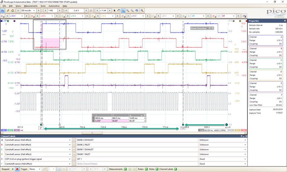
The following waveform shows the customer’s vehicle captured at idle speed with all VVT-i controllers disconnected. This allowed the camshafts to return to their default position (No VVT-i intervention). I have then highlighted our inspection points for camshaft and crankshaft correlation measurements. Here I chose the first rising edge of each camshaft signal after the missing teeth of the crankshaft prior to the ignition event of cylinder 1.
You can find further information on dynamic valve timing and correlation checks here:
https://www.picoauto.com/support/topic18471.html
https://www.picoauto.com/support/topic21754-10.html
The rotation rulers identify two crankshaft revolutions (720°) and are located at the bottom right-hand corner of the scope screen. With 720° of crankshaft rotation identified on the screen, we can use the time rulers to measure the relationship between the crankshaft and the first rising edges of our chosen camshafts (in terms of crankshaft rotation). Below we have Bank 2 Exhaust Camshaft at 6.458° of crankshaft rotation after our 0° rotation ruler and the Bank 2 Inlet at 94.84°.
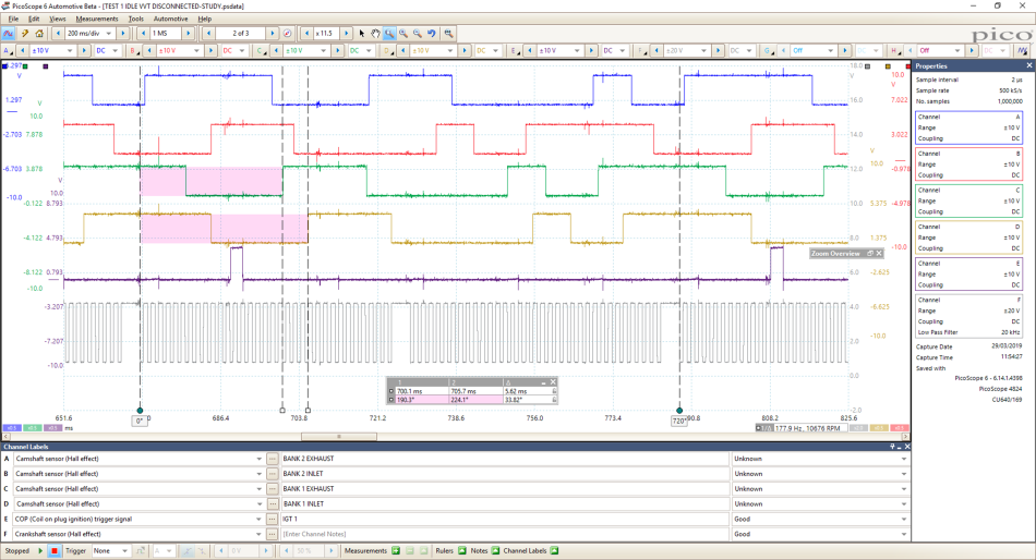
The process for Bank 1 camshafts is repeated below returning values of 190.3° for Bank 1 Exhaust and 224.1° for Bank 1 Inlet.
The million-dollar question once again is “What does a good one look like?”. Normally at this point, we refer to the Waveform Library for a known good waveform, but at the time of diagnosis, a known good waveform was not available.
You can find more information on the power of the Waveform Library here.
Thanks to our colleagues at Toyota UK, we located another vehicle we could use for comparison measurements, in the form of a Lexus RX350. While this is not a direct comparison, the engine codes were the same (2GR-FE) and as the saying goes “when it’s all you got, it’s all you got”.
Once again, the same procedure applied to the donor vehicle. The fault codes were checked (all clear), VVT operation was confirmed using the active test feature of the scan tool, and finally, the VVT controllers were disconnected to ensure that all camshafts return to their default position. This ensures that we, as near as possible, are “comparing apples with apples” beyond a reasonable doubt.
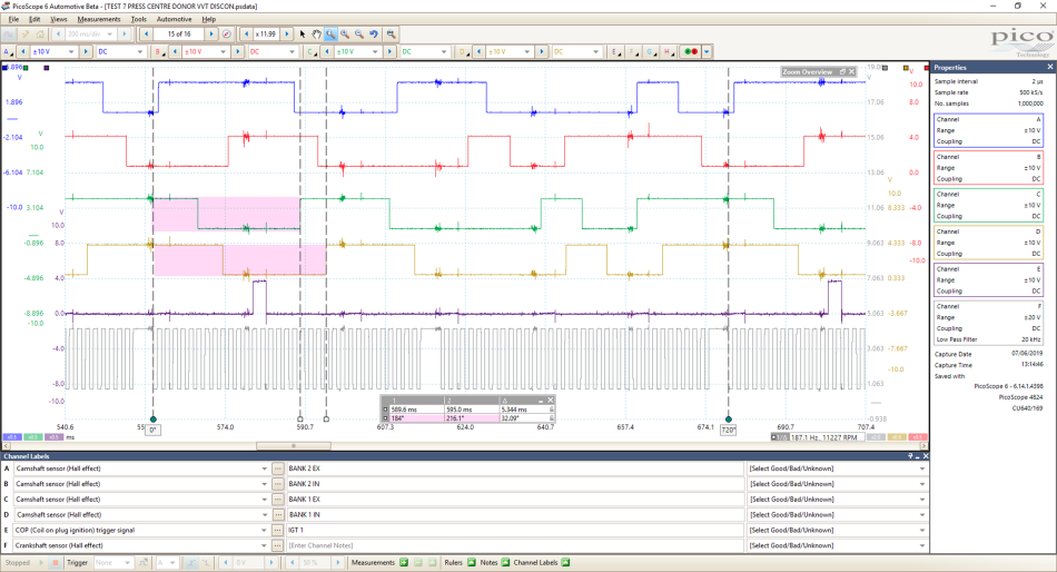
Starting with Bank 2 of our donor vehicle below, we can see that the correlation between camshafts and crankshaft are comparable with the customer vehicle.
Bank 2 Exhaust Camshaft 6.435° of crankshaft rotation after our 0° rotation ruler and Bank 2 Inlet at 93.7°. Taking all the variables into consideration, these values are a near perfect match to our customer’s vehicle (Bank 2 Exhaust 6.458° and Bank 2 Inlet at 94.84°).
The process for Bank 1 camshafts of the donor vehicle is repeated below, returning values of 184° for Bank 1 Exhaust and 216.1° for Bank 1 Inlet. Here we finally have the error we were looking for and, more importantly, this matches the fault reported by the PCM (P0016 - Camshaft Position Correlation (Bank 1 Sensor A).
Summary of PicoScope analysis
| Customer vehicle | Donor vehicle | Calculation | Error (Crank° / 2 = Cam°) |
| Bank 1 In 224.1° | Bank 1 In 216.1° | 224.1° – 216.1° = 8° | 8° Crank = 4° Cam |
| Bank 1 Ex 190.3° | Bank 1 Ex 184° | 190.3° – 184° = 6.3° | 6.3° Crank = 3.15° Cam |
| Bank 2 In 94.84° | Bank 2 In 93.87° | 94.84° – 93.87° = 0.97° | 0.97° Crank = 0.485° Cam |
| Bank 2 Ex 6.458° | Bank 2 Ex 6.435° | 6.458° – 6.453° = 0.005° | 0.005° Crank = 0.0025° Cam |
But how could this be possible when the static valve timing check confirmed no error? Without a doubt, we have a sufficient deviation in the correlation between vehicles for Bank 1 camshafts. Given that our donor vehicle has no camshaft correlation fault codes we can conclude that our customer’s vehicle Bank 1 camshafts are retarded by approx. 4°.
How can we have a deviation of almost 1° (0.85°) between Bank 1 inlet and exhaust camshafts?
This could be a “stretching” or fluttering timing chain, worn timing sprockets, gears, tensioners, slippers or even oil pressure.
I can confirm there was no oil pressure symptoms and no timing chain/engine rattle throughout the entire coolant temperature range. In hindsight, I wish I had measured the oil pressure but as you will see it proved not to be relevant.
At this stage, I don’t have all the answers but whatever this is, it has the ability to deviate the camshaft and crankshaft correlation by values that differ between camshafts and Banks. Looking at the pick-up ring for our crankshaft sensor we have 34 teeth (36 – 2) to denote one engine revolution (360°).
Sticking with 36 teeth to simplify the maths, 360° / 36 teeth = 10° degree of crankshaft rotation for one tooth and one gap of the pick-up ring. This is the best resolution (minimum crankshaft movement) we obtain when trying to determine the amount of crankshaft rotation via the scope using tooth count alone. However, by using the rotation and time rulers we can measure between the pick-up teeth, which gives infinite resolution and the ability to detect minuscule movement of the crank and camshafts.
With this information in mind and access to the original VVT controllers (with integrated camshaft timing gear), we have 36 teeth on the inlet camshaft timing sprocket and therefore 18 teeth on the crankshaft timing sprocket.
360° of Engine rotation / 18 teeth of the crankshaft timing sprocket = 20° of engine rotation for every tooth of the crankshaft timing sprocket.
20° of crankshaft rotation = 10° of camshaft rotation, which could be detected by counting crank sensor pulses alone, however, our camshafts are retarded by approximately 3 to 4°, which can only be measured as mentioned above via the rotation and time rulers.
We can, therefore, conclude that our primary timing chain (Crankshaft to inlet camshafts) has not jumped a tooth as our dynamic valve timing check would return a camshaft error of 10° for all camshafts not just Bank 1 inlet. We could, however, have a timing error between Bank 1 secondary timing chain connecting the inlet to the exhaust camshaft, but the technician confirmed the bright links of the timing chain to be aligned with their respective markers to all timing gears. Remember, both Bank 1 camshafts are retarded by a minimum of 3.15°! Now, where do we go?
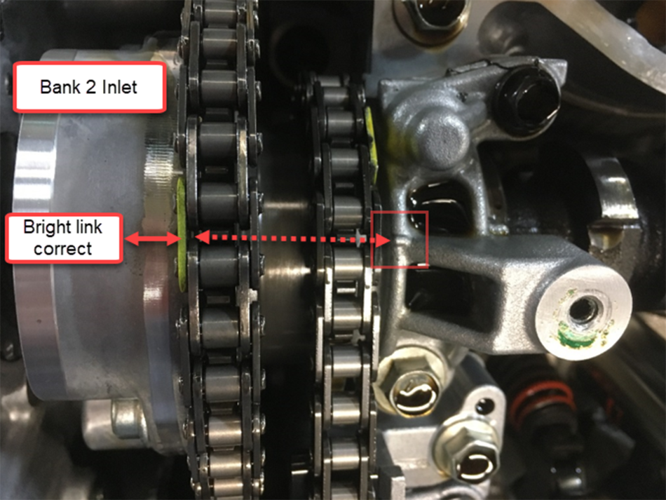
Back to basics once again: We removed the cam covers and checked the static valve timing for alignment. The initial inspection confirmed good alignment of all timing marks with the visible bright links located correctly. However, to throw a curve ball in here, if the engine was rotated numerous times clockwise, then shuffled back anti-clockwise before settling clockwise (in order to qualify the static valve timing), the timing marks looked suspicious and inconclusive for the Bank 1 inlet camshaft.
The Bank 1 inlet camshaft timing is inconclusive given that the alignment drifts with repeated engine rotation.
The Bank 2 inlet camshaft timing has conclusive alignment with repeated engine rotation.
Based on the evidence gathered above, we decided to remove the engine and inspect the timing chain assembly.
Unfortunately, it was not possible to visit this engine during the repair procedure or postfix, however, the following images speak volumes.
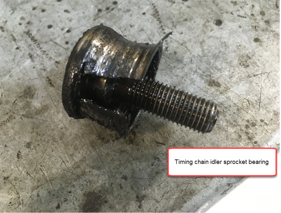
Below we have excessive eccentric wear of the timing chain idler sprocket allowing the tension between Bank 1 inlet camshaft and the idler to periodically “relax” (depending on engine load), which resulted in the camshaft timing deviation.
Notice the debris and deposits in the oil residue about the inner circumference of the idler sprocket. Removal of the idler confirmed excessive “shell” bearing wear due to lubrication starvation from a blocked oil passage to the idler shaft. The passage was contaminated with the identical residue found about the idler sprocket which begs the following question:
Did the idler bearing fail and block the oil passage or did oil contamination block the passage resulting in bearing failure? (Given we have no vehicle history I would go with the latter).

While we could not attend the vehicle postfix, I have liaised with the team involved in the repair and can confirm that the vehicle has been returned to the customer after extended road testing without any further issues (MIL Light remains extinguished and engine faults codes are clear).
Timing chain idler sprocket, shaft, bearing, chainset and associated consumables
The original fault code P0016 referred to Camshaft Position Correlation (Bank 1 Sensor A - Intake) which niggled me for some time as you would expect such sprocket wear to affect other camshafts. During a conversation with the repair team it did come to light that occasionally, fault code P0017- Camshaft Position Correlation (Bank 1 Sensor B- Exhaust) had been present, but never any fault codes for Bank 2.
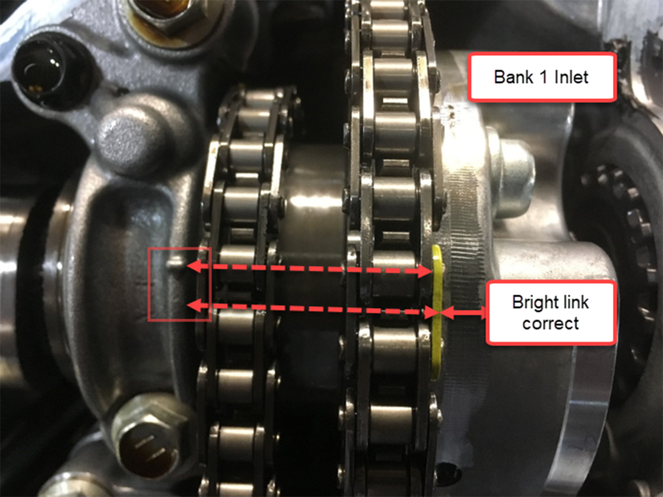
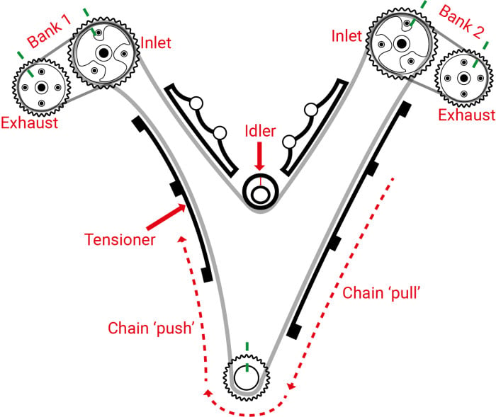
Given the location of the timing chain idler sprocket, we can see how the chain tension is taut on the right-hand side due to the clockwise rotation of the engine generating a nearly permanent “chain pull”, but relaxed on the tensioner side due to “chain push” (hence the location of the timing chain tensioner).
If you were to apply a downward force to the chain idler (see image below) in order to centralise the worn sprocket, both Bank 1 camshafts would rotate slightly and the timing marks align perfectly thanks to the pull/push effect of the crankshaft upon the timing chain. Bank 2 sprockets would remain fixed as the only “purchase or slack” within the chain would come from the tensioner side (chain push).
I have often wondered just how much camshaft deviation is acceptable before the PCM records a camshaft correlation fault code (e.g. P0016). I think we can conclude from this case study that 3° of camshaft deviation is sufficient to generate a fault code but this will differ for each manufacturer.
More Channels. More potential.
The complexities of qualifying valve timing increase proportionally with VVT actuators in conjunction with multiple camshafts, gears, idlers and timing chains. While we can utilise timing marks, bright links, pegs and locking tools to confirm static valve timing, how can we be 100% sure that the valve timing remains true when the engine is running, without checking it dynamically?
Just to play devil's advocate for a moment: let’s assume that during your next diagnostic challenge the valve timing checks out perfectly both static and dynamic. Could you still have a valve timing issue? Most certainly yes, with the onset of hollow camshafts with pressed lobes, worn camshaft followers and incorrect valve clearances. In this scenario, we reach for the WPS500X Pressure Transducer for in-cylinder analysis; like in this forum post: Individual cylinder valve timing errors.
Looking back at other case studies where 8 channels would have been a life saver, the following adventure springs to mind. Here we used the Reference Waveform feature to identify a camshaft correlation issue but as you can see, the possibilities of introducing variables are increased without the additional 4 channels of the new PicoScope 4823.
Having used this scope for a number of site visits I must add that channel labelling and test lead identification has never been more important and it requires an element of discipline to ensure you do not misinterpret test results or introduce measurement errors.
In the following video, I explain my diagnosis and results further:
Kyle
May 04 2020
Great Case Study. I had one of those back a few years ago, except mine was exhibiting random misfire on Bank 2 (good bank) due to fuel trims being altered, but no timing codes. Same process (using scope to monitor cam timing) was used to diagnose, however I only had a four channel, and did not have the nice degree rulers that Pico now has in their software. I also found that bank 1 was retarded due to the bearing failure and wear on the idler bolt. Nice!
mykhaylo roslyak
November 27 2019
wow. what a great learning lesson. i wonder though, why Bank1 inlet - Bank1 exhaust = 32 degrees, while on Bank 2 delta is 87 degrees.
Martin Rubenstein
July 06 2019
Another fascinating case study, with bonus video, too. Without the PicoScope and Steve’s rigorous, precise approach, I wonder what the garage’s next step would have been. Possibly a replacement engine? Just about everything that could be replaced had already been replaced, including the ECU. The skills required for such diagnosis are not dissimilar to those required for aircraft accident investigation. A far cry from the public’s “grease monkey” image.