PicoScope 7 Automotive
Available for Windows, Mac, and Linux, the next evolution of our diagnostic scope software is now available.
Automotive guided tests
Library of examples on how to perform tests when using PicoScope.

Training
Our collection of training videos, articles, guides and information on training courses.

Waveform library
The Waveform Library is a global database of waveforms uploaded by PicoScope users.

Case studies
Real-life case studies show how the professionals use PicoScope to diagnose vehicle faults.

A to Z of PicoScope
Detailed description of various PicoScope software and hardware features.

Videos
Training resources and demonstrations on PicoScope and the Automotive Diagnostics Kit.

Newsletter
Archive of our monthly Automotive Newsletters.

Documentation
Download manuals, brochures, posters, and training materials.

Reviews and awards
Accolades for the preferred diagnostic tool for service centers and vehicle manufacturers.

| Vehicle details: | JCB JS220 |
| Engine code: | 4HK 5.2L |
| Year: | 2007 |
| Symptom: | EGR fault, Engine stalling |
| Author: | Ben Martins |
I have noticed recently how varied things are becoming here at Pico. While the predominant market is automotive, PicoScope is also being regularly applied to other industries.
With the varying cases presenting themselves, getting the chance to spend the day on a big digger was an opportunity not to be missed.
This customer reported that there was black smoke coming from the machine when it was running and when loaded to the maximum, the engine stalled.
Feeling like I’ve gone back to my roots a little with more plant and agricultural cases cropping up, I’m still amazed at the lack of diagnostic assistance available to the technicians. With plant I’ve struggled to see a standard diagnostic port for OBD. This means as an independent technician you need a huge amount of diagnostic equipment to support each machine. This is not practical nor financially viable. That leaves us with our technician experience and the possibility of a manual if you can find one.
The changes now happening within the plant and heavy machinery sector are that machines are becoming more and more advanced, and are faced with tightening emission controls. The old rotary style fuel injection systems, which could easily pass a small stone though the system and still run, are becoming a distant memory. The likes of common rail diesels, AdBlue tanks, DPF’s and ever more sophisticated forms of engine and emission controls are becoming commonplace. This may sound pretty standard for most of us that have been playing with cars but what these machines lack in engine control they make up for in hydraulic control. The level of safety surrounding these machines requires them to be highly accurate when it comes to controlling hydraulic pressure and flow. The engines, installation and controls are also becoming ever more complex. The customer’s report of black smoke and lack of power all sounds too familiar. The need for fast efficient diagnostics is now.
As is the case with most plant and agricultural machinery, the engine isn’t a JCB. This one is an Isuzu 4HK engine.
As seen over the years, vehicle manufacturers will often share powertrains but they try to cover it up with their own labels and plastic trim. With plant it is there for everyone to see!


The many different engine applications and the fact that there may be the exact same machine but with different power outputs, combine to make it difficult to do much research prior to visiting the machine. However, attending the machine I noticed some familiar components, turbo, MAP sensor, crankshaft sensor, electronically controlled injectors, an eight-wire EGR valve….wait, eight wires?
Before looking at the eight wire EGR valve I decided it would be worthwhile investigating some of the engine signals associated with lack of power.
There could be other underlying issues, such as: injectors over-fuelling, blocked intake, poor compression (resulting in incomplete combustion) and others which could result in black smoke and lack of power.
Utilising PicoScope’s four channels I decided to capture the crank position, MAP sensor and cylinder 1 injector current signals, adn having a WPS500X on hand I could determine actual intake manifold pressure. I felt it worthwhile to ensure the MAP sensor was working correctly. Using a ‘T’ piece to insert the WPS500X ensured the MAP sensor output signal would not be disturbed. This is good way to qualify the MAP sensor reading whilst also determining physical pressure.
The capture below was taken with the machine up to operating temperature, engine at operating speed (approximately 2000 RPM), and then in order to repeat the fault the dipper arm was pulled in to deadhead.
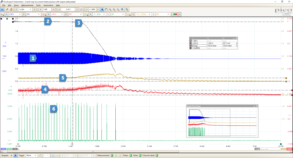
I had to apply channel filtering to get good diagnostic patterns, I have measured a number of different machines now and they all seem to be quite noisy. This is not a problem with PicoScope as we can also apply filtering post capture. The other way to help clean the signal would be to reference to the sensor or actuator ground. Unfortunately, more often than not I have not been able to find a wiring diagram, so battery negative or chassis ground is the next best thing.
With the capture above I have applied 1 kHz of lowpass filter to Channel B to help better understand what is going on. To help highlight changes in the signal, scaling up Channel B has provided more detail. For more information on scaling visit:
https://www.picoauto.com/library/training/scope-school-part-3-tips-and-tricks
One of the first things I notice from the MAP sensor (4), is how closely it follows the physical intake manifold pressure.
Using WPS500X (5), is a great way to confirm the sensor output matches what is physically happening in the system. Not always needed I know, but when serial data is not available qualifying sensor outputs is vital to the diagnosis.
I next brought in rulers to measure the manifold pressure before the machine was placed under load and stalled. I found that at 1900 RPM, the pressure as measured by WPS500X was 133.8 mbar, which the sensor was reporting as 1.332 volts. Remember here that the sensor will have a voltage reference to atmospheric pressure without the machine running. Therefore 0 volts at the MAP sensor does not mean atmospheric pressure, which in this case I measured at 1.07 volts. Is this correct? I couldn’t tell you but having WPS500X in place meant I could be confident that the sensor is reading something when it is reporting 0 bar pressure with the engine OFF and ignition ON.
Looking at the results from WPS500X, 133.8 mbar at 1900 RPM seems rather low, especially as the machine is equipped with a turbo, even with no load applied. I’m not sure what to expect to be honest but I would have thought given the size of the turbo, 200 mbar should be achievable.
By now I’m sure you’re all screaming at me, “CHECK THE EGR” which when creating an action plan of possible causes is going to be on the list.
I checked connections to make sure we had no leaks from the intercooler or the pipework to ensure that the potential boost wasn’t escaping. I did find the EGR pipe from the exhaust was cracked with a significant leak, but not enough in my opinion to bring the MAP so low.

On to the EGR valve. Hurray, I hear you say. Now I’m faced with something I’ve not seen before, an eight-wire EGR plug. I’m sure there are many of you out there that would have come across this but it was new to me. I could just take the pipework off and get on with it, but I like to find out how something works and more importantly provide the customer with the evidence as to what has gone wrong, without risking the bolts snapping!
Not only does this justify my time but helps me better understand the machine for those future times when you are faced with a similar complaint.
Time to search for technical information on this valve!

As I have said on a number of occasions, technical information seems to something of a mystical thing when it comes to these machines. In this case though I was lucky enough to be working with an Isuzu engine and there is a reasonable amount of information available. I managed to find a manual for an Isuzu fuel injection system, which included a basic wiring diagram. Despite this there were some differences and not having the exact manual meant a lot of the data was not relevant but I did find an eight-wire EGR valve on the wiring diagram.

As you can see from the diagram the EGR valve has eight-wires as does the machine. There is a supply, ground, three wires for control and three wires for position feedback. Notice how the EGR valve symbol is depicted: it appears to be in three phases. The use of U, V and W is something we are seeing when looking at Hybrid and Electric motors not EGR valves! With this in mind I decided that finding out if the valve actually moved was next on the list.
With fixed duty engines such as plant machinery, EGR can be used constantly whilst the machine is operating. It is quite common to see a 60 % duty cycle when the machine is being used. To get the ECM to operate the EGR valve, a snap throttle can be used. This isn’t easy without an accelerator pedal but the attempt was made. The idea is that on the overrun we would normally expect to see the valve open fully to allow maximum EGR back into the engine so by observing the engine speed and the three control wires we should hopefully see something. Time to connect the PicoScope.
From the above capture you can see the increase and decrease in engine speed. I am on the correct command wires for each of the three phases. As the engine speed is reduced you will see a command for EGR butwhy are all three finishing at the same time? If they were being controlled the valve would have a more staggered approach to the command signals, in order to move the motor to the correct position using the three phases.
I’ve seen enough. The EGR valve needs to come off to be inspected.


As expected the EGR is completely stuck open.
I can confirm that a new one was fitted and cured the fault. However, PicoScope confirmed the fault before any dismantling took place! Not only this, but I now have data for future use.
To be sure that in the future I have a known good reference, before getting the new EGR valve I removed the motor part of the valve, using its own spring to keep it held in the normally closed position. This allowed me to observe what the MAP sensor should be reading if there was no EGR operation. Great help for the future.

Bringing the engine speed back up to approximately 1900 RPM and measuring the voltage at the MAP sensor, the result was conclusive. I now have 2.5 V at the MAP sensor indicating a rise in pressure. I then loaded the engine by deadheading the dipper ram as before: this time a reduction in engine speed but no stall. No more smoke either.
I did notice how hot the exhaust became. Often EGR is used to cool down combustion temperatures as there is less oxygen in the cylinder to burn. This is fine when we have a demand for increased power but, when in a fixed duty engine, running with EGR closed can cause excessive heat to be generated.
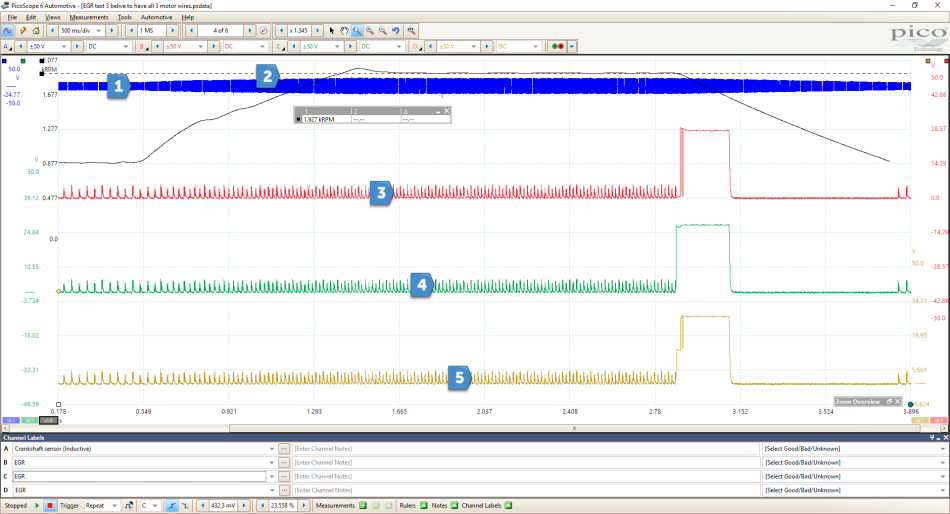
The final piece of the puzzle comes when the EGR valve is fitted and we can see what it is supposed to do when the machine is at operating speed and temperature. The capture below measured crank position, EGR Position and Feedback. With hindsight I should have also included MAP here to observe what happens when EGR is operating and under loading conditions but time was not on my side.


So, you can now see activity almost straight away after the engine RPM has been increased. No load is being applied the engine at this point but it is safe to say that the EGR is being commanded and there is feedback from the position sensors.
I think from the capture above you can determine that on Channel C and at point (3) you are seeing the position feedback for the EGR valve, Channel B and point (2) is EGR command.
If not for the voltage readings it could be the other way around.
Channel B is 28 V implying actuation.
Channel C is 5 V, which I would associate with sensors.
I am making an assumption here purely based on experience and could be wrong. If anyone could back this up it would be most appreciated. Please comment below!
To sum this up I would say it is comforting to know that even when faced with unusual components and limited technical information, there is nothing wrong with applying PicoScope, just to see if anything does happen when we believe it should. Providing a record to support your work and time spent can be as important to the customer as finding the fault quickly.


