PicoScope 7 Automotive
Available for Windows, Mac, and Linux, the next evolution of our diagnostic scope software is now available.
Automotive guided tests
Library of examples on how to perform tests when using PicoScope.

Training
Our collection of training videos, articles, guides and information on training courses.

Waveform library
The Waveform Library is a global database of waveforms uploaded by PicoScope users.

Case studies
Real-life case studies show how the professionals use PicoScope to diagnose vehicle faults.

A to Z of PicoScope
Detailed description of various PicoScope software and hardware features.

Videos
Training resources and demonstrations on PicoScope and the Automotive Diagnostics Kit.

Newsletter
Archive of our monthly Automotive Newsletters.

Documentation
Download manuals, brochures, posters, and training materials.

Reviews and awards
Accolades for the preferred diagnostic tool for service centers and vehicle manufacturers.

| Vehicle details: | DAF CF |
| Symptom: |
It’s been a while since I last worked on a tractor unit and I’d forgotten how impressive and how important these machines are. Keeping them on the road and working is imperative so when an issue arises getting direction quickly, as well as the fix, is vital.
The vehicle was presented with a load of warnings and alarms on the dashboard and so reaching for the scan tool was important to get an insight as to what is triggering the warnings. Whilst the scan tool was busy - scanning - the opportunity to chat to the driver was taken. With no apparent drivability issues prior to the warning lights one thing that was mentioned was the lack of DEF (AdBlue) the vehicle had been using. Traditionally, a vehicle like this would get through a lot of DEF as it’s constantly on the road. The lack of DEF usage was backed up by the fault codes present.

Looking through the codes we can see that a large proportion of them are pointing towards the DEF system. There are also some CAN related issues but the one labelled as high priority is being flagged as a DEF pump failure - Code:P3912. Despite all the DEF trouble codes being inactive, anything related to the DEF system can have a major impact on the engine operation which may well explain the engine protection and engine torque reduction fault codes. Couple this with the customer's information on the fact that the DEF fluid isn’t being used we have a starting point.
As with everything, making sure you know how it should work is vitally important. Fortunately, despite the fact this is a cummins aftertreatment system, it shares a lot of similarities to the Bosch Denoxtronic 2.2 aftertreatment system which we look into on the forum. Operationally, it is pretty much the same. There is a pressure building phase, injection events and then purging once the system is switched off. There are however some slight hardware differences.

The biggest difference between the two systems is that the pressure sensor and the orifice are part of the injector module rather than within the pump. This makes the injector module a lot bigger than the bosch unit but this means the pump assembly is smaller.
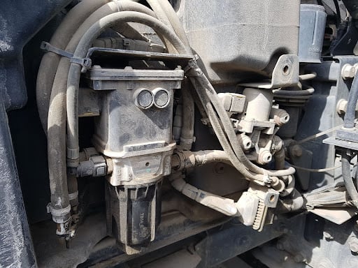
Often overlooked is the visual inspection which should be one of the most important! You can often tell a lot just by using your eyes but don’t stop there, use all the senses you’ve been given! From the pictures above you will see that we have a slight DEF leak at a couple of the joints between the pump and the injector module. As we have a number of fault codes relating to the pressure being too high this would make sense if the pressure stepped outside of the rating of the seals in the pipework. Another thing to note is the fittings on the injector module and the shape of the pipework, especially the bottom hose as it appears to be stretched. Could there have been a modification at some point? The connectors especially are typically the plastic push fit connectors due the high corrosive properties DEF has on certain metals. It’s good practice to make notes of everything you see, hear, smell and feel.

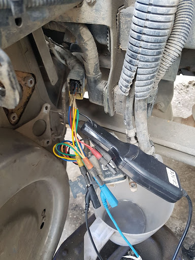
Almost certain we need to look at the aftertreatment system, in particular the DEF pressure. Looking at the wiring diagram we could get these signals at the injector module. The plug is an 8 pin connector but only 6 pins are used and with the positioning of the connector it was easier to use the breakout leads for ease. This isn’t always practical or typically advisable as disturbing the wiring could actually fix any potential problem. Needs must though sometimes and this was the best option for getting the signals we required.
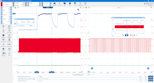
First up then is to take a look at the pressure sensor and by using a current clamp we could see if the injector is trying to operate. By referencing the ground supplied to the injection module we only needed to graph the supply and the output. Should there be an issue with the ground supply we wouldn’t have a stable 5V supply. Unfortunately, just by having the vehicle idling with all the fault codes still present meant the DEF system would not automatically prime itself. In order to test the unit we had to clear the codes and then manually activate the pump through the actuator tests through the scan tool. This allowed us to perform a priming test as shown.

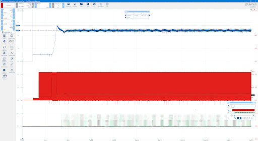
From this capture we can see that the pressure sensor is responding to the changing pressure where it starts just above 0.5V and then sharply rises during the purging phase and gradually continues to rise before the test is stopped and then the drop in pressure. The pressure sensor is exactly 5V which as I’m referencing to the sensor ground gave me confidence that the ground is good.
What is interesting is that the scan tool was reporting a pressure between 10 and 12 Bar. 10Bar is slightly above the traditional 9 BAR we would expect to be seeing for a DEF system suggesting that the fault codes are correct in reporting over pressurisation.
Using the scan tool again to perform an injection test gave further interesting results. This time though we connected to the pump control to see how the ecu reacts to the over pressure.
During this test we can see that the aftertreatment system primes the DEF and the pressure again rises to around 3V and after a period of time the system switches the 2/2 control valve to drop the pressure by purging the system. Once the pressure has dropped it is then tried again. We watched this and it continues this pattern till you stop the test. What was interesting that once the test was stopped on the scan tool it provided some information as to why the test wouldn’t proceed to the injection stage stating that it wouldn’t continue the test if the pressure is too low. Interesting that we have a high pressure issue and so would assume that the test wouldn’t continue for both too high a pressure as well as low.
With having seen both the voltage live on Pico and the pressure reading on the scan tool we can say that the sensor is outputting a value that is reflective of the fault. Considering there are no burst pipes, just some small weeping around the seals, we have to believe there is a blockage. Looking back at the schematic, one place had our attention.
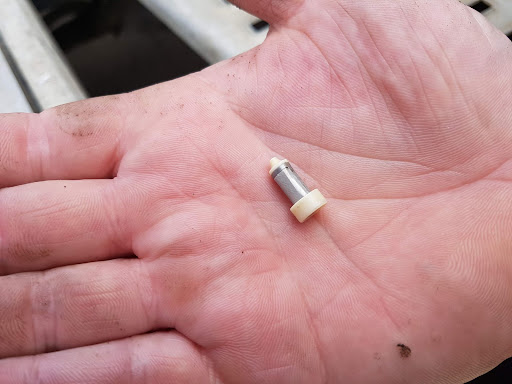
Based on its position, the filter inside the injector module would be first on the action list. It sits after the pressure sensor and if we remember the golden rule that pressure is the resistance to flow, then a blocked filter here would result in the pressure sensor reading a high pressure.
Removing the DEF lines from the injector module is easier said than done but once removed we could see the filter.
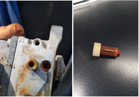
Amazingly the filter was so blocked that it had burst! What’s more it appeared to be contaminated with a dark brown/reddish substance like rust. But how can there be high pressure when the filter is burst? Given that pressure is just a restriction to flow, we have in effect created an orifice so some fluid can pass through the split in the filter but it is still restricting flow.. With the DEF pipes disconnected and any spillage being caught in a container, sampling the fluid from the tank was necessary.
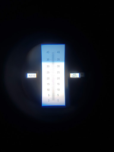
Using a refractometer designed for DEF we can see we have a clear fluid which is sitting around 33%. Ever so slightly above the target of 32.5% but given we don’t have a quality issue it’s not something to be concerned about.
With the driver still with us at this point it was more about continuing with the diagnosis and seeing if this was the problem. Fitting the injector module together without the filter is risky and a thorough cleaning of ports was needed. We were glad that we did clean the module as we did find some finer particles which may have also been adding to the restriction but could also cause a blockage at the injector. Happy that we’ve cleaned it out as best as possible and that the fluid coming from the tank was clear we ran through the scan tool test, hoping that the DEF pressure had been reduced.
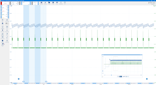
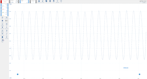
Here we can see that the initial pressure gets to 2.7V and then drops away to around 2.3V and then we see we have activity from the injector. I’m not 100% sure when the aftertreatment ECU determines a high pressure or whether it waits to see if the pressure drops once the pump duty has been dropped to 10%. If we compare the before and after we can see some clear differences.
Using reference waveforms we can bring in the pressure trace captured when the filter was still fitted.
Here it’s clear to see that without the filter there is a clear drop in pressure yet before the pressure continues to rise. With activation now taking place we carried out a quantity test to make sure there were no further blockages.
As we have discussed on the forum, the extra detail you can see with Pico compared to the reports given by serial tools allow you to see much more and give you an overview of the health of the aftertreatment system.
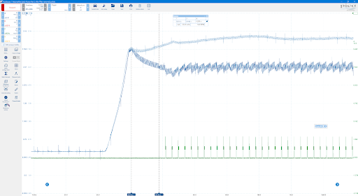
By zooming in to the waveform we can see the saw tooth effect that is taking place. This is caused by the pressure drop after an injection event has taken place. This can be useful in determining whether an injector is partially blocked without removing the unit from the exhaust.
By zooming in further again, you can pick out the ripple generated by the pump. Here, we would be looking for something that looked different or a repeating pattern.
Happy that the rest of the system was working correctly and that the sole cause of our fault codes and warnings was the result of a blocked filter, a new filter was ordered along with the other necessary gaskets and bolts required to complete the job. Once all was refitted and the codes cleared, the vehicle was left to run and observed with Pico to ensure that DEF was injected, which I’m happy to say it did. Thankfully for this vehicle the filters are available separately through the VM. What I found interesting is that the same system is used by other manufacturers yet you cannot buy these filters on their own. This would mean the whole module would have to be replaced which seems extremely wasteful considering you can prove the rest of the system is working correctly. By replacing just the filter we saved the customer just under £1500.
The question still remains though as to what caused the filter to block in the first place. Given how clean the fluid was from the tank to the injector module was this something breaking down in the module? One theory brings us back to our observations at the beginning of the diagnosis. The fittings used to join the pipework from the tank to the injector module appear not to be original. We do know that DEF has certain corrosive properties which may have caused a reaction to these components which has meant the filter has become blocked by doing its job and filtering this contamination. We didn’t have anything to repair or replace these fittings and with a customer that was waiting the best thing we could do was advise that this may happen again in the future and the remedy would be to replace the pipework from the tank to the injector module.
With all the DEF faults I’ve seen more often than not it’s caused by something else and for the most part the aftertreatment systems are pretty reliable. Fortunately the systems have everything already built in which means using existing sensors, feedback and control circuits can all be easily seen with Pico. However, ensuring you know how something works is also vital when it comes to diagnosis. Pico is there to support and capture the evidence required to back up any repair.
Many thanks to Lee Sharp at L&D Commercials for allowing me to join in on this adventure. I hope this helps.


