PicoScope 7 Automotive
Available for Windows, Mac, and Linux, the next evolution of our diagnostic scope software is now available.
Automotive guided tests
Library of examples on how to perform tests when using PicoScope.

Training
Our collection of training videos, articles, guides and information on training courses.

Waveform library
The Waveform Library is a global database of waveforms uploaded by PicoScope users.

Case studies
Real-life case studies show how the professionals use PicoScope to diagnose vehicle faults.

A to Z of PicoScope
Detailed description of various PicoScope software and hardware features.

Videos
Training resources and demonstrations on PicoScope and the Automotive Diagnostics Kit.

Newsletter
Archive of our monthly Automotive Newsletters.

Documentation
Download manuals, brochures, posters, and training materials.

Reviews and awards
Accolades for the preferred diagnostic tool for service centers and vehicle manufacturers.

| Vehicle details: | Manitou |
| Symptom: | Poor performance, Power loss |
| Author: | Ben Martins |
And so, the saga continues… It was time for another visit to the Manitou. This machine was taking up more and more time and, at this stage, we had little to show for it. Let me quickly recap from our previous visits:
We knew that the pump could create 250 bar of pressure with 70 lpm before the valve block. We had captured the fault and believed we had a flow issue. The pressure created due to the resistance to flow was also much lower than that of a known good machine. To try and get ahead of the problem, we acquired an outlet slice which contained the relief valve that sets the working pressure of the machine. We also knew that flow was the underlying problem for this machine and that trying to establish where the oil was going would not be an easy task.
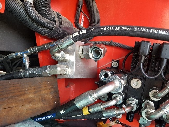
Fitting the flowmeter into the tank line, from the valve block to the tank manifold, seemed like a good plan as this would show us the oil leaving the valve block. We knew the pump could create at least 70 lpm to the valve block, but if we didn’t have 70 lpm coming back out, the oil must be going somewhere else. Fitting the flowmeter is never easy, but we felt it was required to give us some direction.

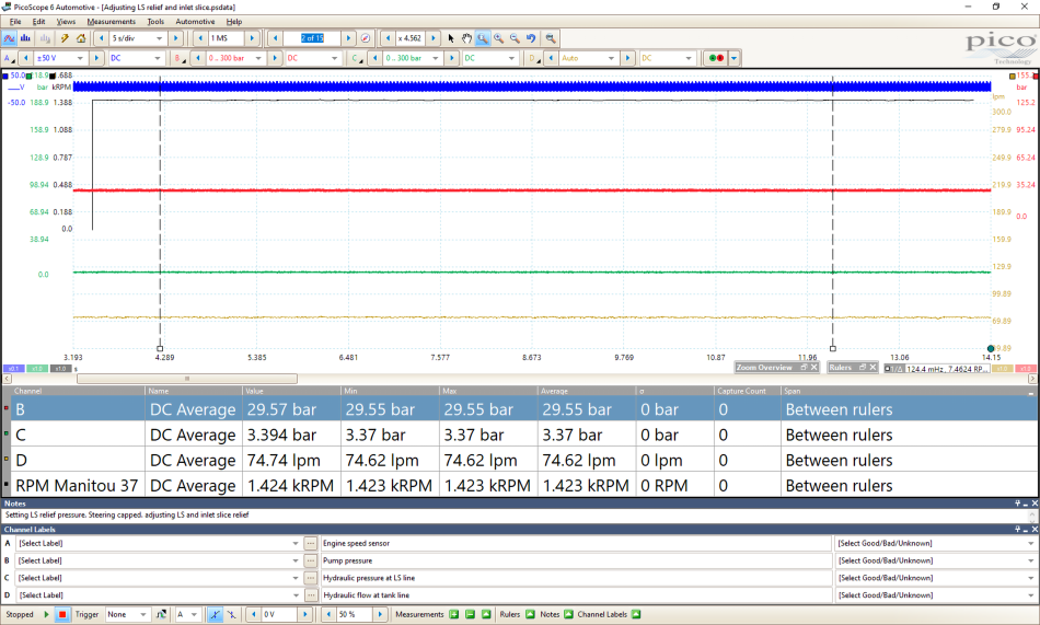
We warmed the machine up and had the engine speed set to around 1400-1500 RPM as per our previous test. With the system in neutral, we could see that there was 29.57 bar of pressure at the pump and 3.3 bar in the LS circuit. More importantly, however, we have 74 lpm of oil flow through the meter. Looking at the hydraulic schematic, we could see that the LS relief valve is a variable one, which could mean that this could come down to the relief valve opening too early and letting the oil flow over the main stage. Oil in a system will always take the path of least resistance. Having the Pico connected meant we could graph the pressure in real-time as we made adjustments to the LS spring. This made us able to ensure that we didn’t surpass the working pressure of the machine.
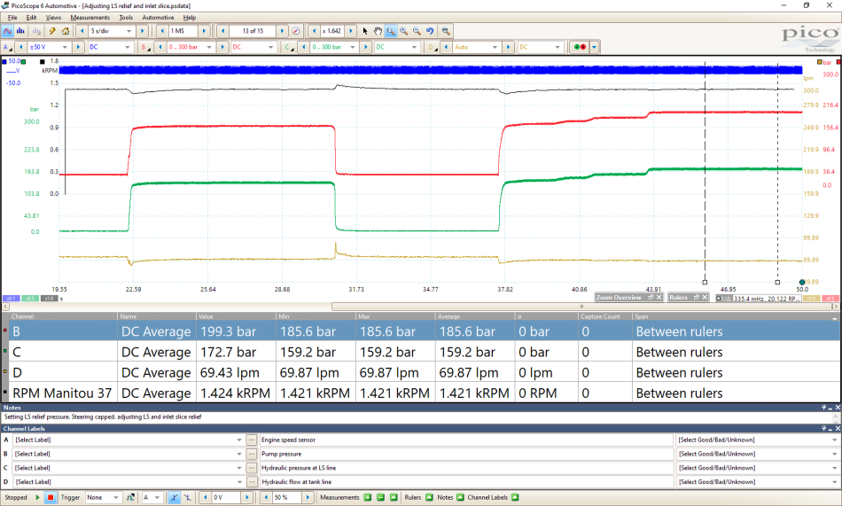
Deadheading the Tele service to make sure that flow is demanded ensures that the LS pressure is increased, which in turn holds the main stage relief valve shut. We slowly adjusted the LS relief valve until the adjustment screw could not be turned any further. As you can see, we still only had 199.3 bar and 69 lpm of oil over the relief valve.
But how can nearly all the oil be coming back through the valve block? The adjustment screw on the LS relief valve was all the way in. This should prevent the valve from opening. We also have a deadheaded ram not allowing oil back to the tank via the DCV. So how can nearly all the oil be coming back through the valve block?
Could it be that the LS relief valve could not be fully seated and, by not holding the main stage closed enough, allowed the oil to pass? Or was the main stage relief valve stuck partially open?
We decided to replace the outlet slice, but this is by no means an easy task. With 15 pipes and an accumulator holding 35 bar worth of oil pressure, you need to make sure that you completely understand what you are doing. Training is so important when dealing with hydraulics, so please make sure you have the correct knowledge and understanding before you work on these systems. This case study should not be used as a guide on how to work with the hydraulics.


We replaced the outlet slice and refitted the valve block. We made sure that the adjustment screw on the relief valve was all the way out to avoid a build-up of pressure in the system in the event of a leak. We ran the machine and checked for warning lights. All was OK and we had no leaks. It was time to start adjusting the LS relief valve.

As we adjusted the valve one turn at a time, we could see the pressure going up with each turn. Surely, we’d cracked it. The pressure just kept going up: 100 bar, 180 bar…
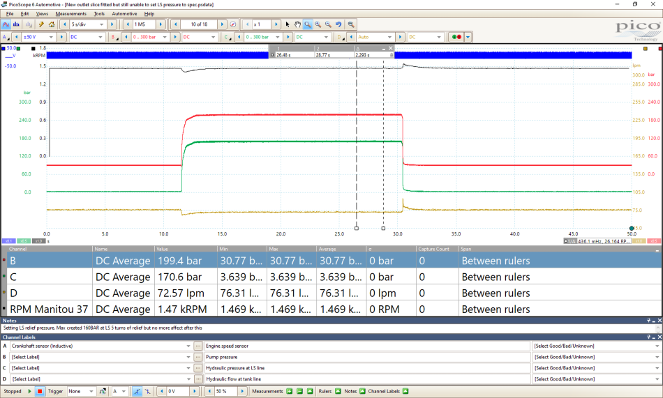
200 bar! However, at this stage, I could no longer turn the adjustment screw on the relief valve. I’d reached the stop on the adjustment again and we were met with the same issue that we had with the old outlet slice. Needless to say, there was a lot of disappointment and some more head-scratching. Going back over what we already knew, we’d now prevented the LS pressure to flow back to the tank which means all the LS pressure is adding to the main stage relief. However, the pump pressure can only achieve 200 bar with a flow rate of 70 lpm, which is near all the oil available. How can the oil be passing over this relief valve? Looking back at the schematic we saw other routes back to the tank that didn’t pass over the relief valve.
There are a couple of routes that the oil could take: through the stabilizers, the steering unit, through the slew motor or across a spool and back to the tank. We decided to cap off these services and see if this was the case. By blanking off the ports, we could see if it altered the pressure as any “escaping” oil would have nowhere to go. Sadly, despite all this, we still couldn’t get the pressure to increase past the 200 bar.
We were now starting to run out of options. It was looking more and more like the oil was returning to the tank via another route other than the relief valve. One idea was to create our own valve block using the slices we have removed. This would allow us to add a directional control valve (DCV), to operate and deadhead a service. Splitting the system this way means that we can determine if a fault is within one side of the valve block or the other.
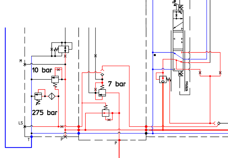
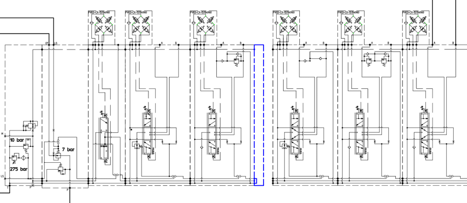
I’ve redrawn the schematic again and removed a section of the valve block to help highlight some of the key points. The main one to notice is the tank line that runs irrespective of the dual-stage relief valve. The slice I’ve highlighted is the Tele service, which is a hydraulic ram. This will not see a great deal of flow back through the return to the tank line in blue. However, with the adjustment screw for the LS relief valve screwed all the way in, we were still seeing 70 lpm coming back to the tank. What if, somewhere in the valve block, there was an internal leak between the high-pressure oil and the very low pressure of the return tank line? And more importantly, how could we prove it?
Time was once again getting the better of us, and we had to call it a day and rebuild the machine so that the customer could use it even with the fault present. Though we were a little disheartened that we still hadn’t been able to point the finger at a specific component, having the recording and backup abilities of PicoScope helped us to show the progress. This is important, as it proves the work that has been done. However, time is money and there was a feeling of: “How much testing is too much?”.
The plan of attack for this day was already out the window when it started. The flowmeter I had been using was required elsewhere, which meant I was unable to capture any flow measurements during the day's tests. Being unable to measure the flow wasn’t ideal, but we were reasonably convinced that the oil was not going anywhere else other than back to the tank through the outlet slice of the valve block. In the hope of getting some direction, we decided to split the valve block in half. This would mean removing the valve block again and reposition the end slice to sit between the Tele slice and where the slew slice would originally have been. If there is an internal leak over a DCV spool or between the slices, we could hopefully get an idea of which side the fault was on.
As I’ve mentioned before, removing the valve block like this carries many risks, contamination being the most severe. Keeping a clean area was imperative as we wrestled the valve block back into place and loosened the adjustment screw for the LS relief valve again. We checked for leaks and then we began to adjust the LS relief screw to increase the pressure.
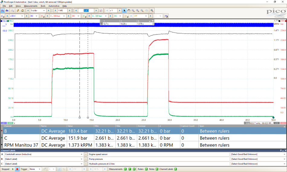
Our first attempt got us to 183.4 bar and our second attempt is visibly higher.
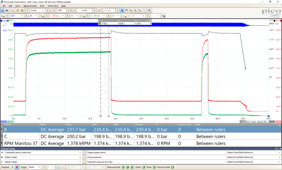
Finally, we broke through that 200 bar ceiling and managed to get to 231.7 bar. At this point, the adjustment screw on the LS relief valve bottomed out again. Not exactly the result we wanted, but we had proven that by reducing the number of slices we saw an increase in the pressure.
We could spend another two days removing and refitting this valve block and removing the slices, but as I’ve mentioned before, there is such a thing as too much testing. In this situation, there was enough evidence to support the theory that the fault was present in the Main Control Valve. Isolating the problem, however, was going to require more time. If you use the golden hour from the automotive world, the matter of time had gone completely out of the window for us! We decided that we could only truly be confident about fixing the machine by replacing the complete valve block assembly. This was not a decision that was taken lightly, but we felt that it was the right option with the evidence we had.
I can confirm that the valve block has been replaced by another company and the operator has informed us that the machine is finally working as expected. I have not had this confirmed, but word is that there was an internal crack in the valve block which was indeed causing the issue. I was also unable to get a confirmation capture, which is a little deflating considering the amount of work that went into the diagnosis. But the customer is happy with the work and effort put into generating the reports and, ultimately, the machine is working as it should so it was overall a success.
There are a few people I have to say thank you to, as this case took up a lot of people’s time! Aaron Teasel– the NFPC trainer, Steve Smith – for a shoulder to cry on when it all went wrong, Pico Technology– for the patience and for giving me the time to support and learn, Tony for his hose creations, and ultimately, Roy from RCT Power Services. I’ve learnt so much from being on-site with Roy and his commitment to looking at a new diagnostic approach can only be commended.
I hope this helps in some way and if you’re a technician working with hydraulics, the case above shows how Pico can offer some new ways of testing that you may not have previously considered.
Martin Rubenstein
July 02 2020
Another great article, Ben, with super photos and screenshots. I really appreciate the moral courage that you (and Steve) show: you could easily write your articles in such a way as to leave out the bits that didn’t go as one would have wished, as well as the dead ends, and make it look as if the PicoScope and the troubleshooting took you in a linear path, straight to the answer (and undermine our confidence in the process), but, instead, you give us an honest, blow-by-blow account, which is far more educational and allows us to learn a great deal more about the limitations and practicalities than we otherwise would have done. Many thanks.
Martin Rubenstein
July 01 2020
Another great article, Ben, with super photos and screenshots. I really appreciate the moral courage that you (and Steve) show: you could easily write your articles in such a way as to leave out the bits that didn’t go as one would have wished, as well as the dead ends, and make it look as if the diagnoses took you in a linear path, straight to the answer, but, instead, you give us an honest, blow-by-blow account, which is far more meaningful and allows us to learn a great deal more about the limitations and practicalities than we otherwise would have done. Many thanks.
Mark
June 30 2020
Thank you for taking the time to document your process, It read like a good novel. Cheers!


