PicoScope 7 Automotive
Available for Windows, Mac, and Linux, the next evolution of our diagnostic scope software is now available.
Automotive guided tests
Library of examples on how to perform tests when using PicoScope.

Training
Our collection of training videos, articles, guides and information on training courses.

Waveform library
The Waveform Library is a global database of waveforms uploaded by PicoScope users.

Case studies
Real-life case studies show how the professionals use PicoScope to diagnose vehicle faults.

A to Z of PicoScope
Detailed description of various PicoScope software and hardware features.

Videos
Training resources and demonstrations on PicoScope and the Automotive Diagnostics Kit.

Newsletter
Archive of our monthly Automotive Newsletters.

Documentation
Download manuals, brochures, posters, and training materials.

Reviews and awards
Accolades for the preferred diagnostic tool for service centers and vehicle manufacturers.

| Vehicle details: | Toyota Hilux |
| Year: | 2007 |
| Symptom: | Engine stalling, Engine vibrations, Non-starter, P0200, P0340, P0355 |
| Author: | Pico | Steve Smith |

25 MHz 700 V Differential Oscilloscope Probe x10/x100
*At Pico we are always looking to improve our products. The tool used in this case study may have been superseded and the product above is our latest version used to diagnose the fault documented in this case study.
When it comes to diagnosis there has to be a logical approach at all costs without any preconceptions about "What could be and what has been?".
The subject vehicle in this case study demonstrates the application of such a philosophy. We have the arrival of a barely driveable Pickup truck; after the classic scenario of a trader purchasing the vehicle at an auction as a runner. To clarify, the vehicle in question was a 2007 Hilux 2.5 Diesel Manual with 145000 miles and looked like it had lived in quarry for most of its life.
The running symptoms were numerous with warning lights flashing, engine start and stalling, severe engine rattle under brief running conditions and excessive smoke via the exhaust. So where do you start? It has to be the beginning.
The all-important customer interview reveals all the answers that can help with some form of clarity when carrying out the initial assessment. The customer had mentioned how he had viewed the vehicle days before at a local auction but it would not run. An auto electrician was called and miraculously on the day of the auction the vehicle did run (of a fashion) meaning a better price could be requested!
A basic inspection was carried out to assess wiring, connections, fuel quality, fault codes and some initial basic live data. This in itself revealed numerous faults that would link the sequence of events prior to the poor running condition.
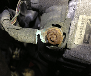
The basic inspection confirmed fuel quality to be good, but engine bay and cabin wiring to have been modified, the alternator wiring to be severely corroded, and 2 x fault codes P0340 and P0335 along with the symptom start and stall. The live data revealed reasonable engine speed, good immobiliser data, a cranking signal set to ON (cranking or not), and no injection feedback values during brief engine run conditions! Given the engine would not run long enough to assess the charging system the fault codes had to be pursued remaining mindful of the recently modified engine wiring!
P0340 refers to No Camshaft position sensor signal and P0335 refers to No Crankshaft position sensor signal to the powertrain control module (PCM) either during cranking or engine running! On the surface this would appear to be a fairly conclusive and relevant code to the symptom and the first port of call was to inspect the signal from both these sensors at the PCM, whilst monitoring the alternator output armed in the knowledge that the alternator wiring was severely corroded (one test to cover numerous components).
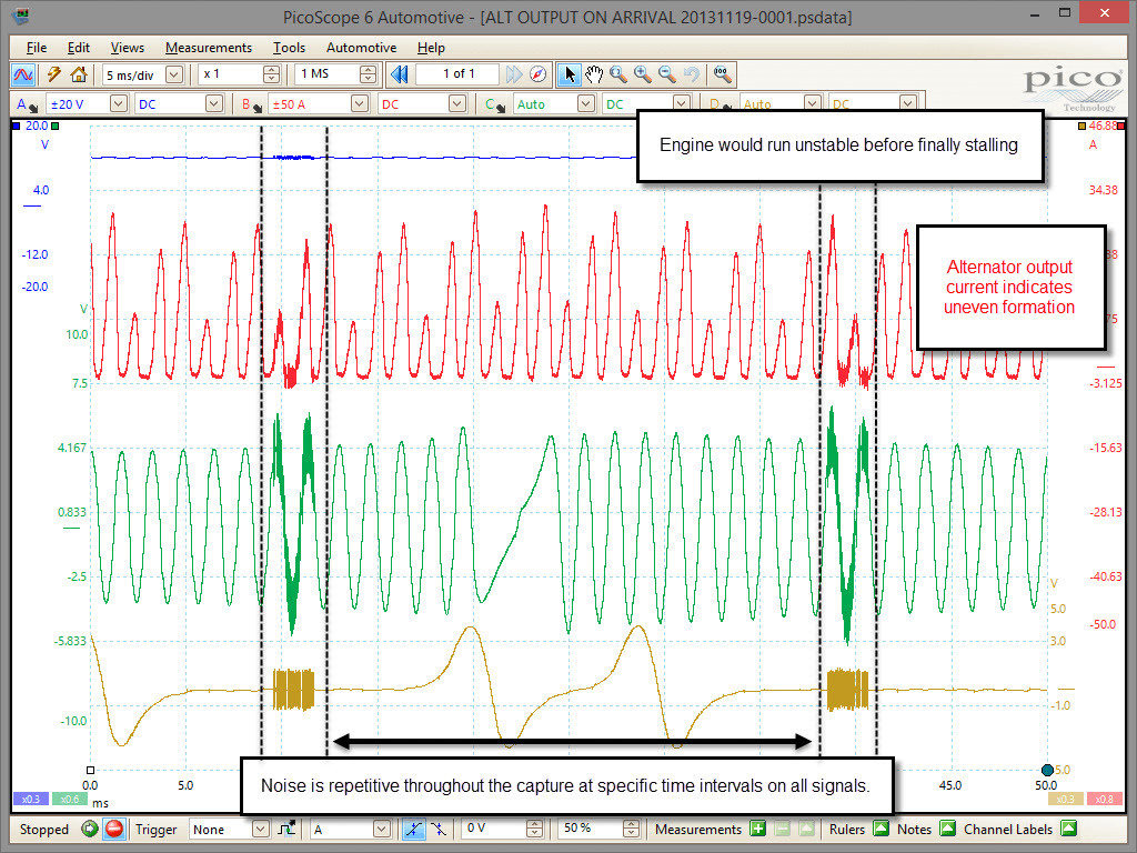
Immediately we can see a good cam and crank signal but with noise evident at periodic times throughout the trace dependent on engine speed, in addition a concern arose with the alternator output captured above during one of the rare moments the engine speed achieved approximately 1000 rpm.
Time to take stock at this point as the PCM reports no cam or crank signal yet both are present and the alternator most certainly has stability issues given the uneven current peaks with a battery voltage fixed around 12.2 volts!
Armed in the knowledge of a large consumer being the source of the noise and one that is triggered at periodic intervals throughout the engine cycle we had to look at injectors.
To remove the charging system from the equation, the alternator was disconnected and harness insulated, whilst a stable battery support unit was installed.
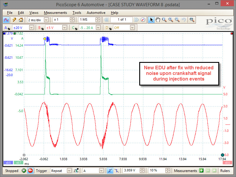
A second capture of the Cam and Crank sensor was then taken using the PicoScope and a current clamp placed around the power supply wiring to the injector electronic driver unit (EDU). Here we can now see that the source of the noise visible on the cam and crank signals was indeed directly linked to the injector operation, and not related to charging or unstable power supply.
The EDU current waveform also revealed poor switching, instability, and insufficient amplitude applicable to injector operation.

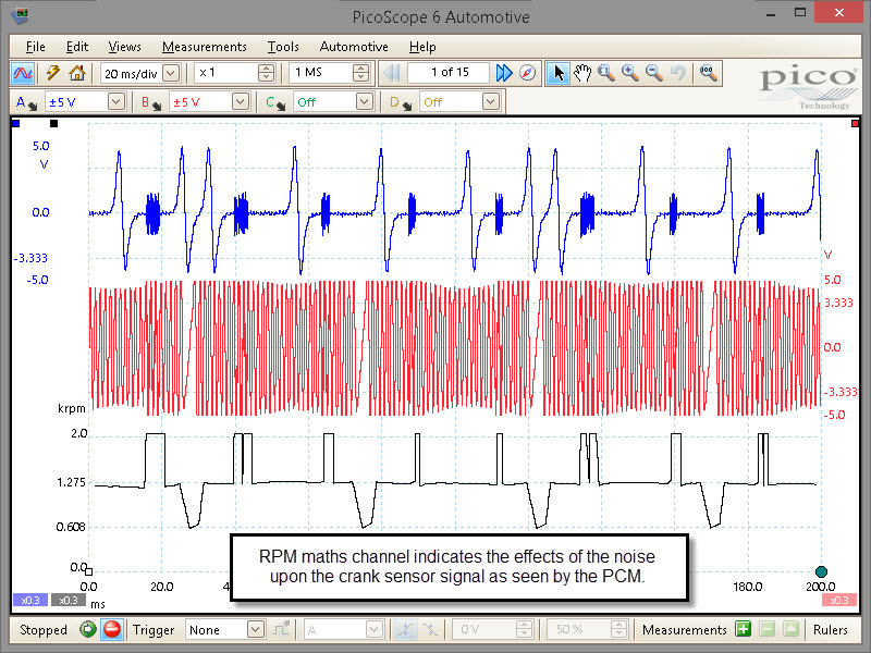
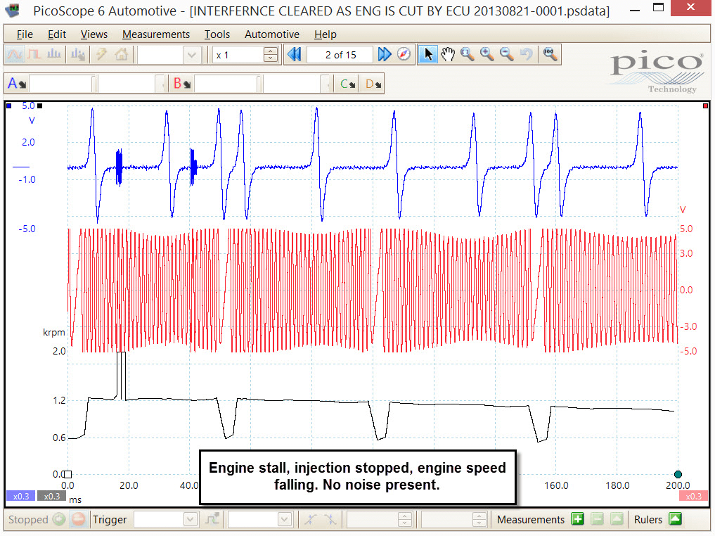
To reinforce the theory that the injectors were most certainly the cause of our noise issue, we were lucky enough to have PicoScope running whilst the vehicle cut out. The video and images below demonstrate how the noise is present during the sporadic injector operation, but clears when injector operation is halted as the engine continues to rotate and slow to a stop.
Within the video we have included an RPM maths channel to indicate the reduction in engine speed during the stall. What is interesting about the maths channel is how the effects of the noise are clearly visible and seen as additional pick-ups within the normal 36-2 peaks (teeth) of the crankshaft sensor signal. This would most certainly effect the count calculation made by the software during cranking/engine running.
See video below:
Time to stop and evaluate what we know:
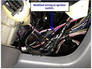
Armed with the information supplied by the customer re: “an auto electrician was called”, and the fact that the wiring had been modified, we had to look at the starter motor signal set to ON. Looking at the wiring diagram for this vehicle the STA (stator) terminal at the PCM was measured and found to be fixed at +12 V with ignition on regardless of whether the engine was cranking or not. Further investigation confirmed the ignition switch wiring to have been modified and the starter motor energise wire cut and joined to the ignition wire (inside the cabin at the ignition switch). The starter motor energize wire inside the engine bay had been cut and a cable installed running back to the original starter motor terminal at the ignition switch. This enabled the vehicle to crank as normal from the key, but for the PCM to receive the crank signal regardless of key position, such as IGN on...why was this?

When dealing with modified vehicles it is always in the back of your mind that the modification could well be the source of the problem and so the best way to overcome these niggles is to revert the vehicle back to standard. This way we are all on a level playing field and the technical data we have is once again relevant.
The ignition switch was rewired as per standard and the engine cranked whilst monitoring the data list. Now the goal posts really had shifted as the live data reported starter motor signal is set to ON when cranking and OFF when not cranking (as per normal). The vehicle failed to start and codes P0335 and P0340 had cleared, but were replaced by codes P0069 and P0200! Now we were confused, but realised the symptoms were now back to the point where the customer had originally set eyes on the vehicle as a non-runner.
P0069 refers to “MAP sensor barometric correlation” issues (not relevant at this stage), whilst P0200 refers to “Injector circuit open/short” which does fit well with our symptom of non-start.
So why does the PCM not see P0200 with the ignition starter motor circuit wired incorrectly. I have to confess here that I did not know the answer and had to research and beg information from a number of engineers until they surrendered the answers.
The starting phase of an engine is subjected to a “Mask period” during cranking where the PCMÂ switches to a basic fuel map whilst the starter signal (STA) is set to ON. Basically it looks at cam and crank for synchronization using a counting technique.
Based on the correct sync and number of teeth everything else can be ignored from a monitoring point of view. It’s almost like the PCM closes its eyes during cranking (other than counting), and hopes for the best! Once started and set conditions are met (such as engine speed above a threshold level and STA terminal to 0 V), the system can then switch to the relevant running map, go to full monitoring of various sensors/actuators and so generate any relevant codes.
When you think about it, it’s a wonder how the vehicle ever starts given the pulsations of a misfiring and jolting engine during unstable cranking, and the amount of noise evident during cranking whilst attempting to trigger injectors with only cranking voltage (testament to engineering if ever there was one).
You have to admit the auto electrician who managed to get this vehicle running (in a fashion) for the auction did know his stuff, but it does feel like Superman was using his powers to do bad!
Armed with the knowledge above, chasing P0200 then became paramount and so the diagnostic path for this code could be followed with confidence.
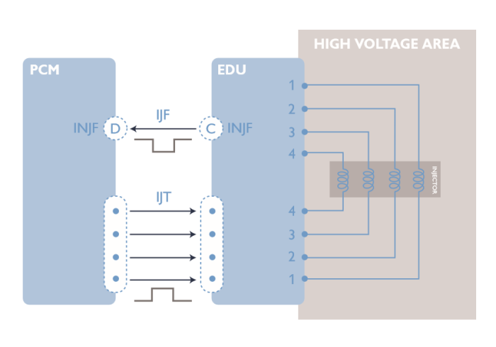
P0200 is set by the PCM when a sequence of Injector trigger (IJT) signals are sent to the EDU from the PCM and the incorrect number of Injector fail (IJF) signals are returned.
For every IJT signal sent, the PCM must receive an IJF signal (think of the IJF signal as confirmation of correct injector operation).
The IJF signal is formed as a result of voltage drop across a resister in series with each injector. This voltage is monitored by the EDU and of course, voltage drop is directly proportional to current flow. Should the current increase/decrease through the injector above or below a predetermined threshold, the monitored voltage will respond accordingly and IJF will not be sent from the EDU to the PCM.
Time to recap again before we go further.
P0200 diagnosis
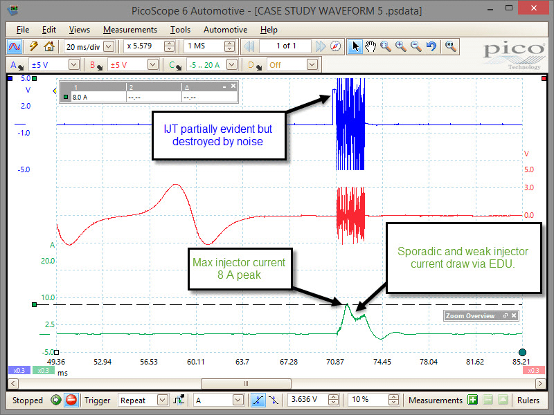
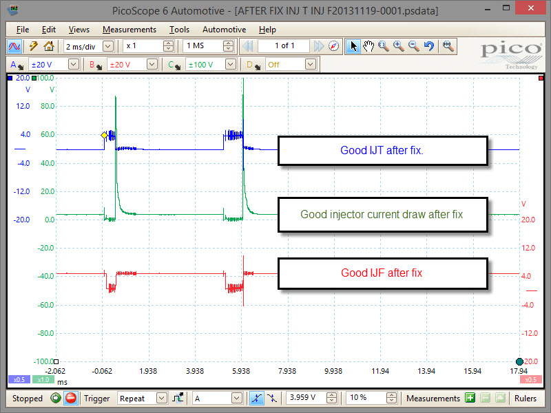
We know we need IJT (Injector trigger) to receive IJF (Injector fail) and so the scope was set to view the presence of the IJT signal. What is apparent from the scope trace below is the fact that the PCM is sending the IJT signal, but more importantly, how the noise generated by the sporadic injector operation almost destroys the IJT signal.
Below we can see no IJF signal response from the EDU to the PCM, only noise.
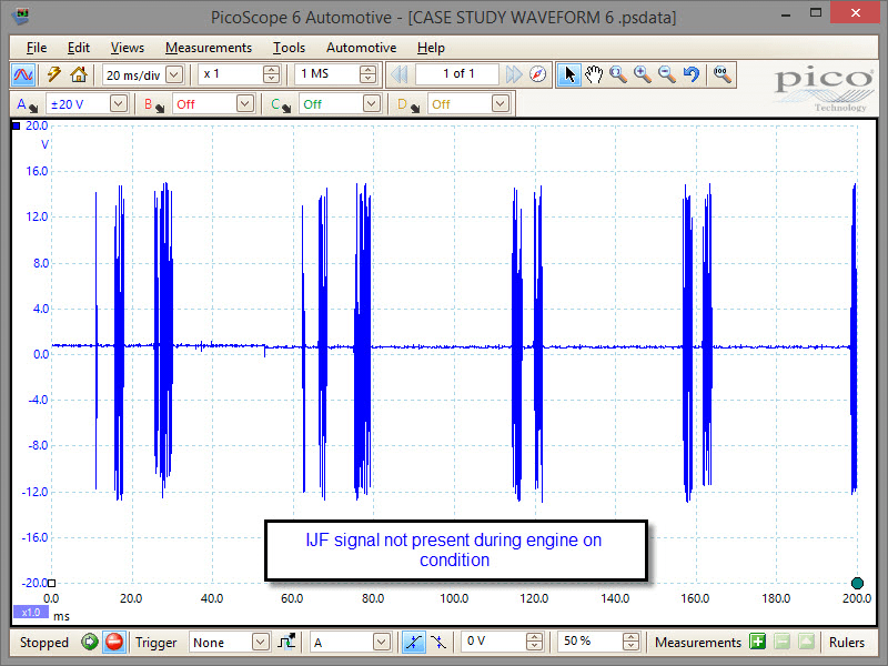
P0200 fault code refers to Injector circuit open or short.
We know IJT is present but poorly formed due to noise/interference (PCM therefore OK). We also know an attempt is being made by the EDU to send IJF, but that this signal has no viable formation that can be interpreted by the PCM. We can also see that each injector is drawing current but with insufficient amplitude and shape could we have 4 x faulty injectors? Very unlikely!
The injector circuits were inspected for continuity, resistance values (across injectors) and for adequate power/ground to the EDU, all were fine with no issues.
The EDU was therefore replaced, the vehicle ran fine and all codes erased.
There often comes a point through many diagnostic procedures where a decision has to be made on the replacement of a component.
When a methodical diagnostic procedure has been followed evaluating cause and effect “analysing the right thing with the right tool, in the right way at the right time” (to quote Lord James Dillon) beginning as always with that all important customer interview, we can be safe in the knowledge that any component replaced has been done so backed up with sequenced logical testing, evaluating test results whilst applying our system knowledge, years of experience and relevant training.
For any further information, please contact support@picotech.com.
Marc
November 22 2020
Hi
great job.
What is the correct injector voltage? I’ve the same engine and I have 71Volts ...
Thabo Tshabalala
July 31 2020
Many thanks for the information, I have changed the crankshaft position sensor twice. Now I know what is the next appropriate step as per your article. Most informative.
Regards, Thabo South Africa
rimvydas
March 25 2015
very nice job!good way of thinking and a lot of tech info you got.I"m impressed.
good luck
mark mckeen
December 05 2014
great job and very thorough diagnostic approach to this unique problem !!
Roger
December 03 2014
As an electronic engineer I would be most unhappy at the level of noise still remaining even though the system now works. What is causing the noise? It looks like the fix is marginal and possibly only temporary.
Barrie
December 02 2014
Whew! still trying to keep up,left me behind after third operation-well done ,Steve
Marc
December 02 2014
Wel done and nice reading of course !
Sean Mc Gettigan
December 02 2014
Nice logical case study and good use of the powerful pico, well done Steve.
George
December 02 2014
Very well done. Very educational. Many thanks for this lecture. I learn a lot from this posting. Thank you for high quality of PicoScope still copies posted.
Regards
George - South Australia
Adam Pierce
December 02 2014
I wonder how long this diagnosis took?
Matt Williams
December 01 2014
Great article Steve! Very informative following a logical approach and showing once again the value of the scope - keep up the good work!
Mark Rabone
December 01 2014
We do occasionally find these ‘curly’ ones! Information from the customer is crucial for a correct diagnosis. How often do we find that someone else ‘who knows about cars’ has already had a look and possibly done more damage than was the initial fault.
Good logical progression for the diagnosis!
Picoscope at it’s best….


