PicoScope 7 Automotive
Available for Windows, Mac, and Linux, the next evolution of our diagnostic scope software is now available.
Automotive guided tests
Library of examples on how to perform tests when using PicoScope.

Training
Our collection of training videos, articles, guides and information on training courses.

Waveform library
The Waveform Library is a global database of waveforms uploaded by PicoScope users.

Case studies
Real-life case studies show how the professionals use PicoScope to diagnose vehicle faults.

A to Z of PicoScope
Detailed description of various PicoScope software and hardware features.

Videos
Training resources and demonstrations on PicoScope and the Automotive Diagnostics Kit.

Newsletter
Archive of our monthly Automotive Newsletters.

Documentation
Download manuals, brochures, posters, and training materials.

Reviews and awards
Accolades for the preferred diagnostic tool for service centers and vehicle manufacturers.

| Vehicle details: | BMW 545 E60 |
| Engine code: | N62 |
| Year: | 2003 |
| Symptom: | Non-starter, Poor acceleration |
| Author: | Pico | Steve Smith |
I don’t know about you, but there are times when I cringe at the amount of technology loaded into one vehicle and the potential for things to fail. The good news is, the more they load in the more opportunities pour out when they go wrong. Here is one such vehicle that has been suffering from repeated breakdowns as a result of what proved to be overvoltage.
To break with case study tradition I can reveal the cause of our customer’s complaint proved to be an intermittent alternator failure which I am sure, comes as no surprise and so you may choose to read no further. However, the real reason for this case study is to highlight the pitfalls we face (both aftermarket and franchise dealer) when presented with technology laden vehicles with intermittent errors.
It would have been very tempting to install an alternator and hope for the best, but using PicoScope and technical information to establish the description and operation of the vehicle power supply system, we were able to prove to our customer an alternator was indeed required.
Remember, if we don’t know how a system functions, we cannot diagnose the system!
Looking back in time, overvoltage would reveal itself as: Headlights flickering brighter than normal, increased heater fan, and wiper speeds, repeated bulb failures and low battery electrolyte level (accompanied with that awful sulphur smell).
With our study vehicle none of these symptoms were present! Here is more about our customer’s symptom: The vehicle could be driven with no issues, then without warning, the instrument panel would light up like a Christmas tree with warnings ranging from "Brake Stability Assistance" to "Active Steering Malfunction" followed by mechanical symptoms such as auto transmission held in a particular gear and no response to gas pedal input.
One event saw our customer start the vehicle after a long stay at an airport car park, drive approximately 6 miles where upon joining slow moving traffic, all the above symptoms revealed themselves leaving the customer limping to the hard shoulder. Here the customer immediately cycled the ignition off and on repeated times whilst attempting to crank the engine (no response from engine/starter motor, instrumentation remained illuminated)
After waiting 5 minutes with the ignition off, the vehicle was restarted as normal and the customer drove with no repeat symptoms... for over 2 weeks!
As always, the customer interview is vital as the information above will prove to be essential during our diagnosis. A basic inspection confirmed no issues around visible connections, no arcing of major components and the wiring harness routing to be correct. The scan tool was attached (a piece of the diagnostic jigsaw) and confirmed 4 control modules to be reporting overvoltage, 2 control modules reporting voltage related issues and the PCM reporting an intermittent alternator communication error.

Once again the scan tool provides invaluable information as to why warning lights and messages have been displayed and more importantly how they relate to one another with a historical sequence of events logged via the "distance indicator".
First report of voltage error (1 occurrence each module)
The Central Body module and Airbag module reported an overvoltage condition at 181760
Second report of voltage error (3 occurrences)
The Dynamic stability control module reported an overvoltage at condition 222380
Third report of voltage error (1 occurrence)
Automatic transmission module reported overvoltage at 223420
Fourth report of voltage errors (7 occurrences)
The PCM reported voltage related issues at 223430
Final code reported has the potential to cause all previously stored codes
The PCM reports an "alternator communication" error at 223440
Here we can conclude overvoltage conditions have been repeatedly detected over a period of time and the majority have occurred during the last 20 counts of the distance indicator, culminating in an alternator communication error code.
To commence the diagnosis of any power related system failure, we must start with battery evaluation and here is where PicoDiagnostics sits perfect, not only with the included battery test but the combined starter motor and alternator test. (One rapid non-intrusive test to evaluate 3 major components):
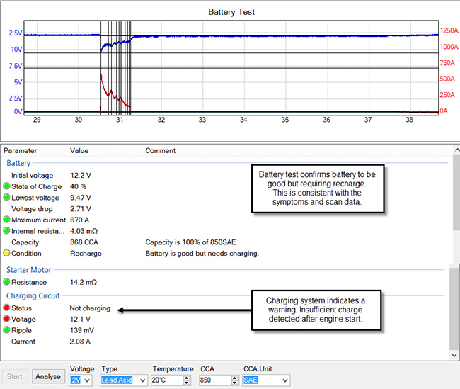
Here the test results were as expected with an initially low battery voltage (12.2 V) and a recommendation to recharge the battery given the communication error with the alternator. The test results have also highlighted a potential charging issue as battery charging would appear to be active but inefficient.
At this point we need to understand how the charging system operates on this vehicle and accurate technical information is key to both system familiarisation and diagnosis (a piece of the diagnostic jigsaw).
Had we been dealing with a conventional charging system where the alternator is "excited" via the charging indicator warning light (with internal voltage regulator), then we would have enough evidence to warrant a replacement alternator. However this is the modern world with a technologically advanced vehicle utilising a "Power Management System" and here we must proceed with caution.
Our alternator now forms part of a network and is controlled through a single communication wire (BSD line-Bit Serial Data) via the Power management software contained within the PCM. Depending on inputs from the battery temperature sensor and IBS (Intelligent battery sensor), accompanied with engine and electrical load signals, infinite control of the charging system is achieved utilizing the alternator output only when relevant and applicable with respect to battery life, fuel consumption, and emissions levels.
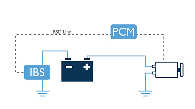
Charging system utilising BSD control
Now we have a multitude of other components to consider when investigating occurrences such as overvoltage. Could the PCM be faulty, what about the IBS, or could this be a network error? It is only right we present ourselves with these questions now rather than installing a component and asking the same questions later when the fault returns.
This is where training and experience come into play (a piece of the diagnostic jigsaw) as we need to take stock of what we know and of course what we don’t. Here, we can then form an action plan on how best to proceed with respect to costs and ease of access:
Based upon the review above a physical check of the charging system was paramount (item 5 above). This would enable evaluation of the charging and control system and could possibly indicate areas of concern.
Using PicoScope (the final piece of the diagnostic jigsaw) our waveform below looks at various aspects of the charging system in an attempt to locate the cause of our overvoltage error. These include the BSD alternator control communication line, output voltage, output current and rectifier/phase winding evaluation.

Here we can see a rapid drop in the output current from a peak of 60 amps to −7 amps which is most certainly uncharacteristic control of a charging circuit given the result upon battery voltage. Whilst infinite charging control is desirable, the effect upon battery voltage should be progressive to prevent undesirable side effects such as lighting flicker etc. Looking at the waveform, the battery voltage does appear to be reaching a level of concern at 15.34 V.
Had we therefore captured the overvoltage event and the operation of the PCM shutting down the charging system (a question that has to be answered)?
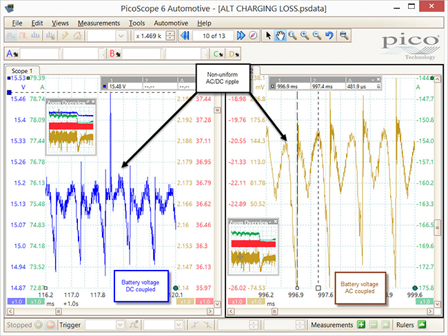
Zooming on channels A and D of the waveform (Battery voltage, AC and DC coupled) we can evaluate the phase windings of the alternator accompanied with the diode/rectifier pack function. Whilst the periodic spikes seen are to a degree characteristic, the typical AC ripple expected from the alternator output was non-uniform and also present in the battery voltage DC coupled. This most certainly points towards an internal alternator component failure or wear within the assembly responsible for charge output, but still does not rule out the control system as a cause of overvoltage.
Knowing the BSD line is directly responsible for alternator output (subject to command from the PCM) the BSD waveform was decoded using the PicoScope decoding feature in an attempt to identify errors within the coded message carried to and from the alternator during the abrupt shutdown (captured above). Using the LIN protocol to decode the BSD line it can be seen that communication continued between the alternator and PCM as Picoscope can decode "packets" of data after the shutdown stage.
Unfortunately we have no way of converting the decoded data to anything of use other than confirming communication to be present. The BSD line carries information specific to the BMW brand and utilises BUS voltage levels identical to a LIN BUS, but the decoded values will be entirely different.

With all the testing to this point we have found evidence to warrant an internal investigation of the alternator but we cannot categorically rule out the PCM or IBS from the equation (items 6 and 7 of our action plan).
One suggestion was to contact the local BMW dealership to ask if they have the facility within their diagnostic equipment to either decode the BSD line or to drive the alternator using an ‘active test’ function (scan tool to command high and low charge output by simulating BSD line command message). To my surprise they do not have such a function within the dealer scan tool, so placing us all in the same boat at this stage of the diagnosis!
There are tools on the market that can simulate such charge control commands as BSD, LIN and PWM signals etc. when it comes to alternator evaluation but these are expensive and generally purchased by reconditioning agents given the value of such a tool in a refurbishing application.
After hours of study I came across a little gem of information that proved incredibly simple yet invaluable to confirming our alternator was in fact the root cause of our overvoltage. What would happen if the BSD line failed between the PCM and the Alternator? Would the battery discharge and vehicle break down? The answer... no!
Should the BSD line become open circuit between the PCM and alternator, the alternator assumes "machine sensed" control and will monitor the charge output internally as with a traditional machine sensed device.
Armed with this information, the BSD line was removed from the alternator and the battery voltage monitored via the OBD socket using the PicoScope. Here we could log battery voltage fluctuations over extended time periods.

At last, undeniable evidence the overvoltage was a result of alternator internal regulation failure and not as a result of BSD control (over 17 V captured with no input from the BSD line). Time now to remove and inspect the alternator with confidence given its challenging location!
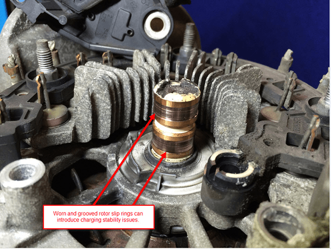

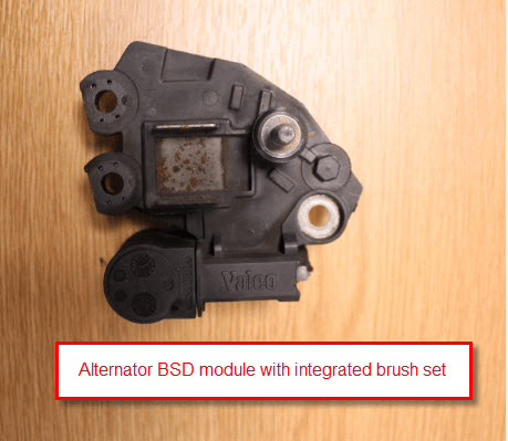

Close inspection of the alternator confirmed no signs of overheating or scorching, but the rotor slip rings revealed a deep wear pattern with "grooving". This condition could introduce charging stability issues and contribute to the non-uniform pattern we can see in the alternator output voltage AC coupled.
I have no doubt the root cause of the overvoltage condition could have been resolved with a replacement BSD module alone, but given the labour involved to remove and replace the alternator, accompanied with the wear pattern present on the slip rings, a replacement alternator was the most cost effective repair with a view to future reliability.

The above waveforms confirm a successful repair with a stable and uniform output voltage both AC and DC coupled (battery voltage stable at 14.81 V).
This case study has opened my eyes to the vulnerability of control modules with respect to input voltage. The effect on vehicle control systems is dramatic should the input voltage become not only too low, but too high. The alternator is a component we take for granted and generally don’t worry about with respect to diagnosis. However, as technology marches on, charging system control will become more complex and no doubt more efficient when integrated into vehicle networks.
Rangarajan Ramabadran
November 18 2020
thankyou for such an exhaustive and scientific troubleshooting procedure. I have been having hair splitting experience with over voltage. Zeroed down to alternator, hope it fixes it. thanks again for the write up!
Edy
February 04 2020
Buenas tardes, tengo un problema con un N62 E70 x5, la bateria carga únicamente cuando aceleró el vehículo si dejo de acelerar, la carga empieza a bajar hasta descargarse totalmente y apagar el vehículo, ya cambie regulador al alternador, ya lo lleve a que le hicieran su servicio, ya probé cambiando IBS y sigue igual carga solo al acelerar, en el escaner me marca “Falta de informe BSD del alternador” 2EBD…... Ya no se que hacer
justino
July 05 2019
Im not smart enough to be a mechanic anymore…
PatM
March 24 2015
Highly informative insight to a situation that given the constraints of flat rate, would have had me throwing an alternator at it after the basic testing and evidence of overvoltage via the fault printout. Excellent homework!
Seth Patterson
March 15 2015
Thank you for taking the time to write this. It inspires me to use our Picoscope in ways that I have’nt considered.
Mark
March 11 2015
Very valuable info thanks
Chris
March 03 2015
I think your final words sum it up best! You’ll never know, where parts we have taken for granted act up in ways we never would have expected - until they do! Great report and thanks for helping us learn!
Dario
March 02 2015
Very interesting case of study. As always, any insights from Mr. Steve are food for thought for all of us. Why not to post this case in the case of study section in the picoauto forum? I would like to take a look to the psdata files.
Kind regards
sigoaprendiendo from picoauto forum
Arnald Govender
March 02 2015
I found the route course analysis of the over-voltge problem most interesting.
Regards
Arnald
Autosparky
March 02 2015
Nice write up
Did you by any chance repeat any test with new alternator? capture the BSD? unplug the BSD to see what it charges without control?
Reckymech
March 02 2015
Nice buddy you have just shown me a potential for the future i am a roadside patrol i have seen this before over volt shutdown but the pico makes life so much better being able to see in real time scope ect . nice Reckymech.
Nino
March 01 2015
I’ve seen this a few years ago now and still see it on a regular basis. Always check system voltage when cold and then you will see 17/18v plus.
Michael
March 01 2015
Well done, how long did it take to find out this was the problem,I work in the field of engine management and I know what it is to track down,some of these fault and without a Oscilloscope it just makes it out of reach to locate and isolate the faults WELL DONE
Malcolm Tripp
March 01 2015
Top marks for excellent diagnosis and informative article, reminds me of the Focus smart charge system.
Brett Hinde
March 01 2015
Hello, Very much liked your article and very I formative.I do agree that deep groove in the alternator slip rings and what looks like the brushes are getting low can cause charging issues Eg.Low or no charging with low brushes and or bad brush connection.This would not cause and overcharging/overvoltage situation.
Cheers Brett
CHRISTOS CHRISTOFI (CYPRUS)
March 01 2015
EXCELLENT!!!
Anonymous
March 01 2015
Great info. I’m active on http://www.m5board.com/vbulletin/e39-m5-e52-z8-discussion/ and AC ripple on an alternator is known to cause multiple module problems, including bus communication between the modules.
Barrie Broomhall
March 01 2015
After 50 yrs in the motor repair trade,I’m getting on in years.I spoken to Steve by phone.
I’ve been studying Pico Scopes for a fair while,to help update my son,would have caught on,unfortunately he is no longer with us.
But reading Steve’s contributions I feel a mental dwarf.
I urge all you switched on blokes out there to gather young ‘uns around you and coach them for the future of our trade.
BUT the wage remuneration HAS to good enough to get the smarter ones into the trade!
Bit emotional but that’s how I have always Felt.
Barrie. Australia
Anonymous
March 01 2015
Great case study! These are very helpful.
Mike Ball
March 01 2015
Very interesting breakdown of the diagnostic process. Not surprised at the lack of dealer ability to run full alternator independent control tests. Some do not even have a ‘scope.
Nice to see the before and after AC/DC coupled voltage ripple waveforms.
Thank you for sharing.
Paul Foster
March 01 2015
I have case study with Volvo V70 with Bosch alternator where the slip rings was worn cause the car charging system and causes the nodes on the CAN-BUS network to shutdown.
We have bi-direction test in VIDA for test procedure for vehicles with BMS ( Battery Monitor sensor)
When using the pico cylinder banlace test does not work with battery monitor sensor.
The Hex code in the serial decoder 3F = Software interrupt. LIN Serial Analyzer is best for decoder
Anonymous
February 28 2015
seems these Valeo regulators have major issues. almost identical issues on the Audis especially the A6 2005>
Ian Petersen
February 28 2015
Great intelligent diagnostic detective work. I realise the car is 12 years old, but the corrosion on the alternator is alarming. Due to road salt and the renowned British climate??
Ian, hot & dry Australia
Martin
February 28 2015
I have worked in the car electronics industry for 30 years and have seen a shift for more inefficiency as a result of too much electronics in cars. If they put less electronics in the cars with less communication between units, it would make it much easier to diagnose a problem. Integration means more inter related unit problems which basically means you don’t know what part of the system is causing the problem in the first place. Take all of that out & cars would be much lighter & do more miles to the gallon which is what we are trying to achieve in the first place. My previous car was some 300Kgs lighter than the one I drive now (same model) but is 50 HP more powerful & gets approx. 10 miles more to the gallon than the previous car. If they made it lighter without all the stuff I don’t need it would probably do 20 miles extra to the gallon!
Mark
February 28 2015
Hey Steve,
Enjoyed your article. You are right - vehicles are becoming more and more complex with electronic hungry components.
It is one thing to have a quality expensive tool in your workshop and another thing to know how to use and another to think out of the box when needed. Sites like this where information is shared gives us all a fighting chance at a positive outcome.
Mario GarcÃa
February 28 2015
thanks for sharing your experience, greetings from Mexico.
Dave Hill
February 28 2015
Excellent article Steve.
This demonstrates nicely just how complex modern systems are & the extreme lengths that technicians (those who care enough to bother) have to go to, in order to make the correct diagnostic call.
The ironic thing is that, many less advanced workshops would have fixed it, based on a more ignorant “experienced based, best guess” approach. Of course they would have some awkward explaining to do if they got it wrong though.
Well done with the diag & repair & thanks for taking the time to put together a well presented explanation of your approach & thought process.
All the best
Dave Hill


