PicoScope 7 Automotive
Available for Windows, Mac, and Linux, the next evolution of our diagnostic scope software is now available.
Automotive guided tests
Library of examples on how to perform tests when using PicoScope.

Training
Our collection of training videos, articles, guides and information on training courses.

Waveform library
The Waveform Library is a global database of waveforms uploaded by PicoScope users.

Case studies
Real-life case studies show how the professionals use PicoScope to diagnose vehicle faults.

A to Z of PicoScope
Detailed description of various PicoScope software and hardware features.

Videos
Training resources and demonstrations on PicoScope and the Automotive Diagnostics Kit.

Newsletter
Archive of our monthly Automotive Newsletters.

Documentation
Download manuals, brochures, posters, and training materials.

Reviews and awards
Accolades for the preferred diagnostic tool for service centers and vehicle manufacturers.

| Vehicle details: | BMW Mini |
| Year: | 2001 |
| Symptom: | Airbag light, Tyre pressure monitor |
| Author: | Darren Cotton | AVC (UK) Ltd |
Using Autologic, I carried out a quick scan; this feature will attempt to connect to every module for that variant. I found that we had no communication for Multiple Restraint System (MRS), Electronic Transmission Management (EGS), Radio (RAD) and Immobiliser (EWS).

Figure 1: Autologic scan results
Maybe the mobile company’s device was telling the truth but maybe unable to handle the repair. This is obviously why we have warning lights illuminated. The advantage of using a high quality dealer level tool is that you know you can trust the information it is telling you. Keeping in mind the customer is just interested in the Airbag and the TPMS warning lights, but is this just one fault? And where do we start…?
Vehicle started and drove fine, Radio OK, but TPMS (tyre pressure monitoring sensor) function not resetting.
The vehicle was left with me and I was able to put a diagnostic plan in place. As stated above, the vehicle started and drove fine, the TPMS is a manual reset function and would not reset. I focused on the Multiple Restraint System (MRS) and looked at the schematics of the airbag system, in fact using the BMW Mini wiring diagram system it made it very easy and a plan of attack was put into place.
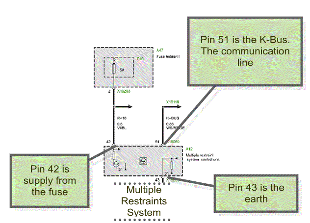
Figure 2: Mini wiring diagram
So I decided to check that the 5 Amp fuse F18 for the MRS, it had a Nominal Battery Voltage (NBV) and was in good order, and the plan was to get access to the MRS module. The module is located under the handbrake lever under the carpet and was not accessible easily, the front seats were removed and the carpet lifted from the rear seats to the front of the vehicle just enough to access the module. With the diagram I was able to check the cavities shown. The supply and earth was in good order.
I wanted to check the communication line as we do have other modules not communicating here, attaching the PicoScope to cavity 51 of the MRS module I was able to see the K–Bus signal; I also located the K–Bus at the O/S/F door sill. Capturing the K–Bus we can see what’s going on here, something was not right. On this Variant the K-BUS wire is White and Red with yellow band (WS/RT/GE).
In Figure 3 below, top and bottom captures are the same, top trace is a zoomed in trace of the lower one. The Green trace is K-BUS at driver’s door sill, and the Red trace is K-BUS at the MRS module cavity 51.

Figure 3: Poor K–Bus signal
The capture above (Figure 3) is one single wire, RED trace is at AIRBAG module and GREEN trace is at Driver’s door sill. Zoomed in, the data being sent was not correct and the input voltage was at 7.5 V this is also incorrect, so now I was getting somewhere, this is our problem and Ijust need to locate the cause…
K–Bus consists of a single copper wire and data transfer is approx. 9.6 kbps (kilobits per second) and is always active when terminal R is switched on. If the bus line is quiet for more than 60 seconds all the control modules that are connected will go into sleep mode. The wire colour is uniform throughout the vehicle, WS/RT/GE (White/Red/Yellow).
Due to the linear structure of the network, K–Bus is available for other modules in the event of a disconnection or failed control unit, Just as the CAN bus, this is referred to as a tree structure with each control unit occupying a branch. The K–Bus provides a diagnostic connection to the control unit connected on those busses. The K–Bus uses only a determined controller to supply B+ for communication. The voltage level must be above 7 V. The nominal voltage should be close to NBV, in my experience a good working K–Bus is around 13 V.

Figure 4: Poor K–Bus signal zoomed in
Studying the wiring diagram it led me to the BCM which on this variant is located in the driver’s side foot–well. Upon removing the module I found water ingress and the wiring harness was soaked… Unplugging the harness the cause was very clear. Corrosion to the terminals at the BCM was so bad that as I unplugged it the pin had broken off.
Figure 5 shows the BCM with the broken pin.
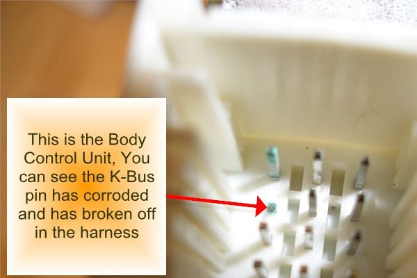
Figure 5: BCM with broken pin
So in a real world this needs a new BCM and a wiring harness, but this is a sales car and they do not spend money, so I came up with a plan.
I opened the BCM and followed the pin back and soldered a wire to the good part inside the BCM.
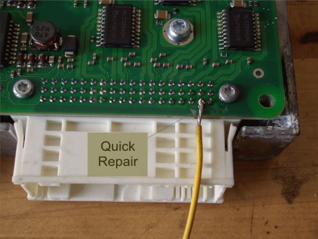
Figure 6: Fixing the problem
I attached the wire to the other side of the multi–plug. After refitting the BCM I carried out a global scan which gave me full communication to all modules, the TPMS reset and all is looking good. Attached the PicoScope to the K-BUS again just for good measure… Which confirmed the repair was a success.

Figure 7: Good K–Bus signal after the repair
Maybe the mobile company who looked at this first are looking for the quick repairs or do not have the confidence of the repair, once the system is understood the process becomes easier and it goes to show that one device is just not enough. The PicoScope in this situation definitely helped in the diagnosis, hard to prove otherwise.
Mike Fenner
December 08 2017
In this case i do not see the scope being of any use other than for DMM function . Upon back probing or unpluging and checking for V-bat voltage and finding 7 v . i would have found the source of the voltage (BCM)unplugged and checked for resistance. Upon doing this i would have found the cooroded terminal and replaced the BCM
Robski
January 03 2013
@ Peter/Allen,
I look at it this way,the connector/pin had already failed due to water ingress & was replaced by soldering the wire direct to the PCB,the same way the original leg to the harness connector was.
The harness connector/plug/socket is open to bad termination/high resistance/water ingress, but the repair from Darren has bypassed the harness connectors & been heat shrunk & sealed making if not a better connection than originally, if the modules were not meant to be removed how do you think these would be wired ? hard wired or have harness connectors ??
How many have cut pretensioner harness connectors out & soldered the wires ?
Have you seen the TSB for the VAG range using crimp connectors for the same pretensioner fault ?
Good job Darren i would be happy to drive that motor & feel that a satisfactory repair was carried out.
allan
January 02 2013
as peter said the “repair” is good for testing and confirming but you should think about replacing the parts as you are liable if it fails in an accident!
benjamin cogtla
December 21 2012
Good job keep that hard work
Lewis Thombozi
December 21 2012
I am impressed, just reminded me of an incident with a 400KVA stand-by genset. it had this similar problem but took us 3 days to get to the problem, by chance of course, its really worth while investing in this machine. good job Darren.
David Paterson
December 20 2012
Excellent! Great tool the Picoscope. I really find it hard to understand why more garages aren’t convinced that this is not just a handy tool, it’s an essential tool. With little training you soon realise that the scope gives the proof that scan tool can’t. For those who don’t understand why, it’s because - as was the case in this example - the scan tool relies on information from sources which aren’t always giving the right - or even any - information. The Picoscope gives concrete proof by being to hook up directly to suspect circuits or components.
As a French distributor for Pico, I’m aware of the reasons why far too few garages have yet invested in the Pico scope, but given that it is now available as a starter kit, there is less reason to be fearful, or hide behind reasons of cost. Make 2013 the year you invest in the Pico Automotive scope and start find both simple and more complex faults. The two together bring in lots of added revenue, as well as customer confidence. Don’t forget you get FREE updates for life when you own a Picoscope!
Nice work Darren!
carl keenan
December 20 2012
A Great piece of diagnostic reasoning! How long has it taken for you to become so competent with the pico & your diagnostic thought process? I have recently bought a picoscope 4 channel & am trying to use it at every opportunity. Have had some success with it with simple engine management issues but would love to learn to use it so much more…especially with K-bus systems. I am finding that accounting for our time with diagnostics is the biggest difficulty. No one wants to pay for your time & everyone thinks that your code reader is a cure for everything.
Peter Clifton
December 20 2012
Nice repair, but by “fixing” it that way, do you not expose yourself to liability should that bodged connection fail, and leave the car without a working airbag system again?


