PicoScope 7 Automotive
Available for Windows, Mac, and Linux, the next evolution of our diagnostic scope software is now available.
Automotive guided tests
Library of examples on how to perform tests when using PicoScope.

Training
Our collection of training videos, articles, guides and information on training courses.

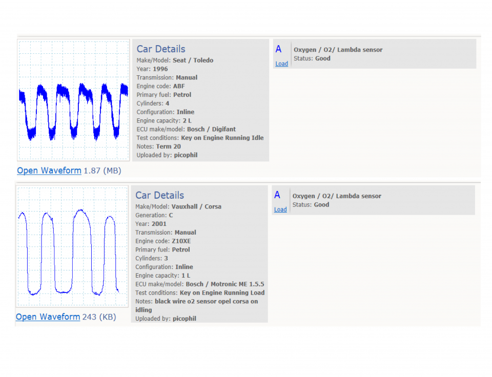
Waveform library
The Waveform Library is a global database of waveforms uploaded by PicoScope users.

Case studies
Real-life case studies show how the professionals use PicoScope to diagnose vehicle faults.

A to Z of PicoScope
Detailed description of various PicoScope software and hardware features.

Videos
Training resources and demonstrations on PicoScope and the Automotive Diagnostics Kit.

Newsletter
Archive of our monthly Automotive Newsletters.

Documentation
Download manuals, brochures, posters, and training materials.

Reviews and awards
Accolades for the preferred diagnostic tool for service centers and vehicle manufacturers.


Back-pinning Probe Set

Flexible Back-pinning Probe

PicoScope Battery Clip
*At Pico we are always looking to improve our products. The tools used in this guided test may have been superseded and the products above are our latest versions used to diagnose the fault documented in this case study.
The purpose of this test is to evaluate the operation of a zirconia type oxygen sensor during engine running conditions based on its output voltage and response time.

View connection guidance notes.
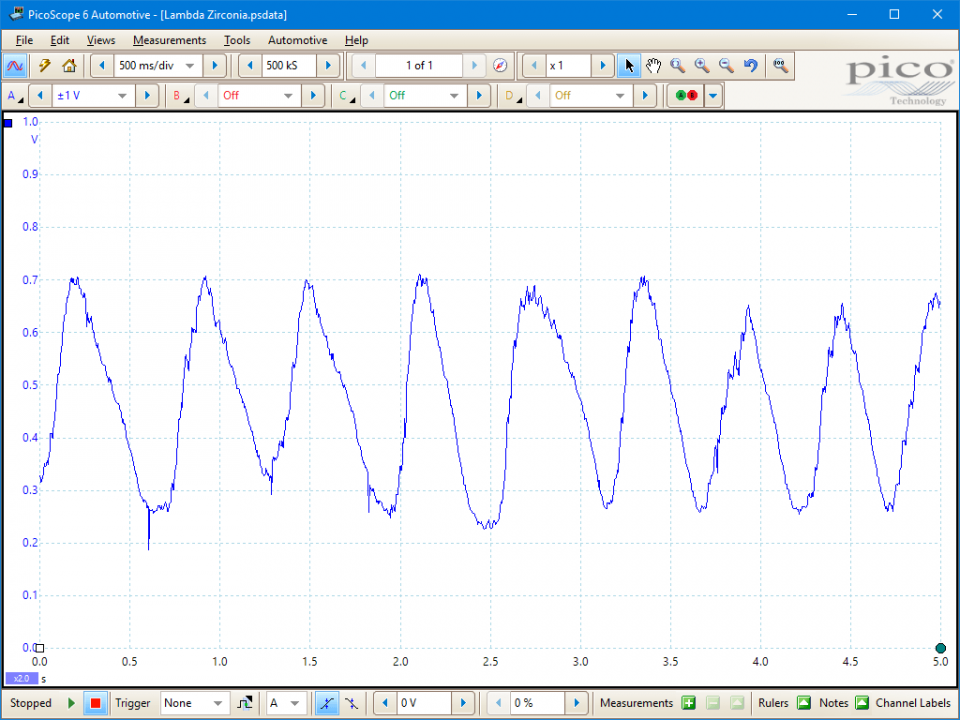
This known good waveform has the following characteristics:
Go to the drop-down menu bar at the lower left corner of the Waveform Library window and select Oxygen / O2/ Lambda sensor.

An oxygen sensor also can be referred to as a Lambda sensor, an O2 sensor, or a Heated Exhaust Gas Oxygen (HEGO) sensor. It is a feedback sensor used by the Engine Control Module (ECM) to perform closed loop control of engine fueling and, if a post catalytic converter sensor is present, monitor catalytic converter function.
Closed-loop control allows an ECM to maintain an almost exactly stoichiometric air/fuel mixture but with small variations between slightly rich and slightly lean to facilitate 3-way catalytic converter operation. These fueling variations cause the switching observed in the sensor voltage output. Typically, an ECM will switch the air/fuel ratio at a frequency around 1 cycle per second.
An ECM only undertakes closed loop control of fueling when the appropriate conditions allow. This is normally during steady-state idle, light load, or cruise operations. When the engine systems are warming up or the vehicle accelerates, the mixture is enriched and the sensors will not exhibit their switching output behaviour.
A zirconia element within the sensor allows ionized O2 to flow from a reference air source to the exhaust gas. The flow is detected by two platinum electrodes either side of the element. The flow rate depends on the partial pressure (the relative O2 concentrations within the reference air source and exhaust gas). A rich mixture will cause a greater flow of ionized O2 across the zirconia element, whereas a lean mixture will cause a low flow. Therefore, a lean mixture is indicated by a low output voltage, around 0.2 V, whereas a rich mixture is indicated by a high output voltage, around 0.8 V.
In general, oxygen sensors will not operate below around 300 °C. As such, some sensors have an internal heating element, which is controlled by the ECM. The heating element raises the temperature to ensure faster control when starting from cold.
Sensor configurations (zirconia type only)
The sensors have varying electrical configurations and may have up to four wires. Sensors without heating elements have only one or two wires. A three wire sensor uses the sensor casing to form an earth connection for the sensor element:
A constant high voltage output from the sensor shows that the engine is running constantly rich and is outside the ECM's adjusting range, whereas a constant low voltage indicates a lean or weak mixture. Under these conditions you can expect to see Diagnostic Trouble Codes (DTCs) related to fuel trim issues from the ECM. The sensor may not be at fault and you should ensure there are no associated issues causing the error codes before condemning the sensor.
Symptoms of a faulty/inoperative oxygen sensor:
Related issues that must be eliminated prior to testing an oxygen sensor:
Typical issues and oxygen sensor faults:
GT022-EN
Disclaimer
This help topic is subject to changes without notification. The information within is carefully checked and considered to be correct. This information is an example of our investigations and findings and is not a definitive procedure.
Pico Technology accepts no responsibility for inaccuracies. Each vehicle may be different and require unique test
settings.
We know that our PicoScope users are clever and creative and we’d love to receive your ideas for improvement on this test. Click the Add comment button to leave your feedback.


