PicoScope 7 Automotive
Available for Windows, Mac, and Linux, the next evolution of our diagnostic scope software is now available.
Automotive guided tests
Library of examples on how to perform tests when using PicoScope.

Training
Our collection of training videos, articles, guides and information on training courses.

Waveform library
The Waveform Library is a global database of waveforms uploaded by PicoScope users.

Case studies
Real-life case studies show how the professionals use PicoScope to diagnose vehicle faults.

A to Z of PicoScope
Detailed description of various PicoScope software and hardware features.

Videos
Training resources and demonstrations on PicoScope and the Automotive Diagnostics Kit.

Newsletter
Archive of our monthly Automotive Newsletters.

Documentation
Download manuals, brochures, posters, and training materials.

Reviews and awards
Accolades for the preferred diagnostic tool for service centers and vehicle manufacturers.


Back-pinning Probe Set

Flexible Back-pinning Probe

PicoScope Battery Clip

Premium Test Lead: BNC to 4 mm, 3 m
*At Pico we are always looking to improve our products. The tools used in this guided test may have been superseded and the products above are our latest versions used to diagnose the fault documented in this case study.
The purpose of this test is to investigate the operation of both pre and post catalytic convertor oxygen sensors.
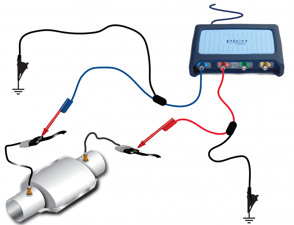
View connection guidance notes.

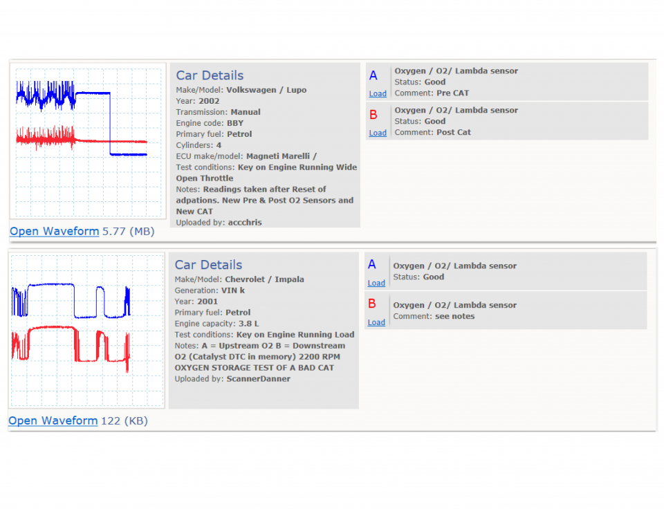
These known good waveforms have the following characteristics:
Go to the drop-down menu bar at the lower left corner of the Waveform Library window and select, Oxygen / O2/ Lambda sensor.
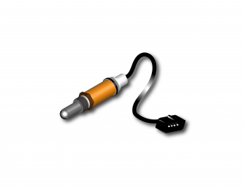
A lambda sensor is also referred to as an Oxygen or O2 sensor, or a Heated Exhaust Gas Oxygen (HEGO) sensor, and plays a very important role in control of exhaust emissions on a catalytic-equipped vehicle. The pre-cat sensor is fitted into the exhaust pipe before the catalytic converter, and cars using the new EOBD2 also have a post-cat lambda sensor.
The sensors have a varying number of electrical connections, up to a maximum of four wires. They reacts to the oxygen content in the exhaust system and produce a small voltage depending on the air/fuel mixture seen at the time. The voltage range, in most cases, varies between 0.2 and 0.8 volts: 0.2 volts indicates a lean mixture and 0.8 V shows a richer mixture.
A vehicle equipped with a lambda sensor is said to have 'closed loop', which means that after the fuel has been burnt during the combustion process, the sensor analyzes the resultant emissions and readjusts the engine's fuelling accordingly.
Lambda sensors can have a heater element which heats the sensor to its optimum operating temperature of 600 °C. This enables the sensor to be located further away from the heat source at the manifold to a 'cleaner' location. The sensor is inoperative below 300 °C.
The lambda sensor is essentially two porous platinum electrodes. The outer electrode surface is exposed to the exhaust gases and is coated in a porous ceramic, with the inner coated surface exposed to fresh air.
The most commonly used sensor has a Zirconia element, producing a voltage when there is a difference in oxygen content between the two electrodes. This signal is then sent to the Electronic Control Module (ECM) and the mixture is adjusted accordingly.
Titania is also used in the manufacture of another type of lambda sensor that offers a faster switching time than the more common Zirconia sensor. The Titania Oxygen sensor differs from the Zirconia sensor in that it is incapable of producing its own output voltage and is therefore reliant on a 5-volt supply from the vehicle's ECM. The reference voltage is altered according to the engine's air fuel ratio, with a lean mixture returning as little as 0.4 volt and a rich mixture producing in the region of 4.0 volts.
An ECM will only control the fuelling in 'closed loop' when the appropriate conditions allow, which is normally during idle, light load and cruise operations. When the vehicle accelerates, the ECM allows overfuelling and ignores the lambda signals. This also happens during initial warm-up.
Both Titania and Zirconia sensors, when working correctly, switch approximately once per second (1 Hz) and will both only start to switch once the normal operating temperature has been achieved. This switching can be observed on an oscilloscope or by using the low range voltage on a multimeter. On an oscilloscope, the resultant waveform should look as the illustration above. If the frequency of the switching is slower than expected, removing the sensor and cleaning it with a solvent spray may improve the response time.
A constant high voltage output from the Zirconia shows that the engine is running constantly rich and is outside the ECM's adjusting range; whereas a low voltage indicates a lean or weak mixture.
A switching voltage on the post-cat sensor indicates that the gases are passing across the catalytic converter's ceramic monolith without being subjected to chemical change and therefore the cat requires replacing with a known good unit, providing that the pre-cat waveform is within specification.
A typical Zirconia lambda sensor has four wires. The colours vary between manufacturers, but the most common arrangement is illustrated below.
Top wire: White heater (+)
2nd wire: White heater (-)
3rd wire: Black - signal
4th wire: Grey - earth
GT128-3
Disclaimer
This help topic is subject to changes without notification. The information within is carefully checked and considered to be correct. This information is an example of our investigations and findings and is not a definitive procedure.
Pico Technology accepts no responsibility for inaccuracies. Each vehicle may be different and require unique test
settings.
We know that our PicoScope users are clever and creative and we’d love to receive your ideas for improvement on this test. Click the Add comment button to leave your feedback.


