PicoScope 7 Automotive
Available for Windows, Mac, and Linux, the next evolution of our diagnostic scope software is now available.
Automotive guided tests
Library of examples on how to perform tests when using PicoScope.

Training
Our collection of training videos, articles, guides and information on training courses.

Waveform library
The Waveform Library is a global database of waveforms uploaded by PicoScope users.

Case studies
Real-life case studies show how the professionals use PicoScope to diagnose vehicle faults.

A to Z of PicoScope
Detailed description of various PicoScope software and hardware features.

Videos
Training resources and demonstrations on PicoScope and the Automotive Diagnostics Kit.

Newsletter
Archive of our monthly Automotive Newsletters.

Documentation
Download manuals, brochures, posters, and training materials.

Reviews and awards
Accolades for the preferred diagnostic tool for service centers and vehicle manufacturers.


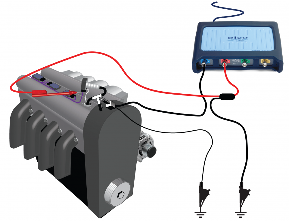
Secondary ignition pickup (capacitive with BNC)

HT Extension Lead

PicoScope Battery Clip

Multimeter Probes
*At Pico we are always looking to improve our products. The tools used in this guided test may have been superseded and the products above are our latest versions used to diagnose the fault documented in this case study.
The purpose of this test is to investigate the correlation between the ignition trigger and secondary HT events in a COP type ignition coil.
WARNING
This test involves measuring a potentially hazardous voltage.
Please ensure you follow manufacturers' safety instructions and working practices and ensure the rated voltage for all accessories you are using meets or exceeds the expected voltage.
WARNING
Uninsulated HT pickups are designed to clip around double-insulated HT leads only – they are not designed for direct connection to a hazardous live voltage.
To prevent injury or death, when connecting or disconnecting an HT pickup:
View connection guidance notes.
Note
Preparation for the test will require disconnection, removal and reconnection of the suspect coil unit.

The waveform above shows the relationship between the secondary HT on channel A (blue trace) and the digital trigger signal (red trace). When the trigger signal goes high, the coil's primary circuit is closed, causing a current from the battery to flow through it. At the end of the dwell time, the trigger signal returns low, breaking the primary circuit and causing the secondary winding to generate a high tension (HT) voltage.
Go to the drop-down menu bar at the lower left corner of the Waveform Library window and select, COP (Coil on plug ignition) trigger signal
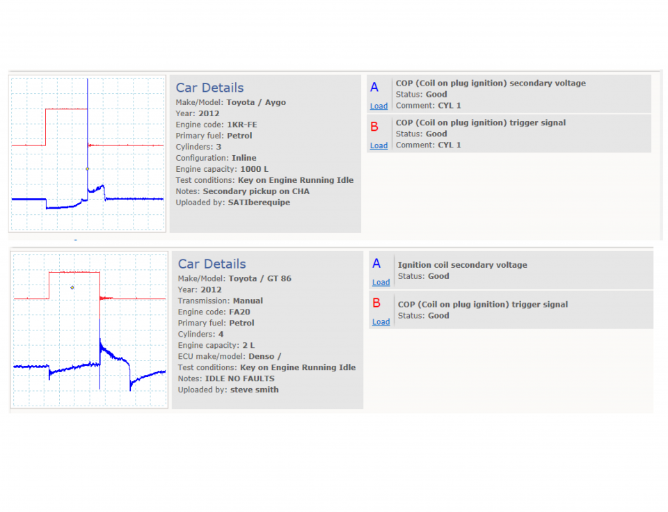

As the illustration is a dual trace picture, the two traces will be explained one at a time.
The low tension (LT) signal switches between 0 volts and 4 volts. When the trigger signal reaches 4 volts, the coil switches on and the 'saturation' or 'dwell' time begins. As the voltage returns to zero, the current in the coil's primary winding switches off, the magnetic flux in the iron core collapses, induces a voltage in the secondary, and the HT voltage is generated.
The coil switch-on and switch-off times are determined by the vehicle's Electronic Control Module (ECM). The dwell time on an engine with electronic ignition is controlled by the current limiting circuit in the amplifier or ECM.
In a constant energy system, the dwell time is fixed regardless of engine speed. This allows the coil to saturate fully and maximises the strength of the magnetic flux. The dwell angle, measured relative to a complete engine cycle of 360°, increases as the engine speed increases.
The modern engine management system with Coil-Per-Cylinder (CPC) ignition has all the advantages of a constant energy electronic ignition system, with the added bonus of eliminating the distributor cap, king lead, rotor arm and plug lead. Reliability problems from dampness and tracking are now almost eliminated.
Unlike a conventional Distributorless Ignition System (DIS) which fires the plugs with both a negative and a positive voltage, CPC only fires the plugs with a negative voltage, improving plug life and increasing the service life of the plugs.
Inside the coil's primary winding is the secondary winding. This is coiled around a multi-laminated iron core and has approximately 20,000 to 30,000 turns. One end is connected to the primary terminal and the other to the coil tower. The High Tension (HT) voltage is produced by mutual induction between the primary winding and the secondary winding, the central soft iron core serving to intensify the magnetic field between them.
The voltage measured at the spark plug is the voltage required to jump the plug gap under varying conditions. This voltage can be affected by any of the following:
Example pin data for two, three and four pin COP units.
GT137
Disclaimer
This help topic is subject to changes without notification. The information within is carefully checked and considered to be correct. This information is an example of our investigations and findings and is not a definitive procedure.
Pico Technology accepts no responsibility for inaccuracies. Each vehicle may be different and require unique test
settings.
We know that our PicoScope users are clever and creative and we’d love to receive your ideas for improvement on this test. Click the Add comment button to leave your feedback.


