PicoScope 7 Automotive
Available for Windows, Mac, and Linux, the next evolution of our diagnostic scope software is now available.
Automotive guided tests
Library of examples on how to perform tests when using PicoScope.

Training
Our collection of training videos, articles, guides and information on training courses.

Waveform library
The Waveform Library is a global database of waveforms uploaded by PicoScope users.

Case studies
Real-life case studies show how the professionals use PicoScope to diagnose vehicle faults.

A to Z of PicoScope
Detailed description of various PicoScope software and hardware features.

Videos
Training resources and demonstrations on PicoScope and the Automotive Diagnostics Kit.

Newsletter
Archive of our monthly Automotive Newsletters.

Documentation
Download manuals, brochures, posters, and training materials.

Reviews and awards
Accolades for the preferred diagnostic tool for service centers and vehicle manufacturers.


Multimeter Probes

Back-pinning Probe Set

Flexible Back-pinning Probe

Large Dolphin/Gator Clips
*At Pico we are always looking to improve our products. The tools used in this guided test may have been superseded and the products above are our latest versions used to diagnose the fault documented in this case study.
The purpose of this test is to investigate the operation of the idle and full throttle position switches.
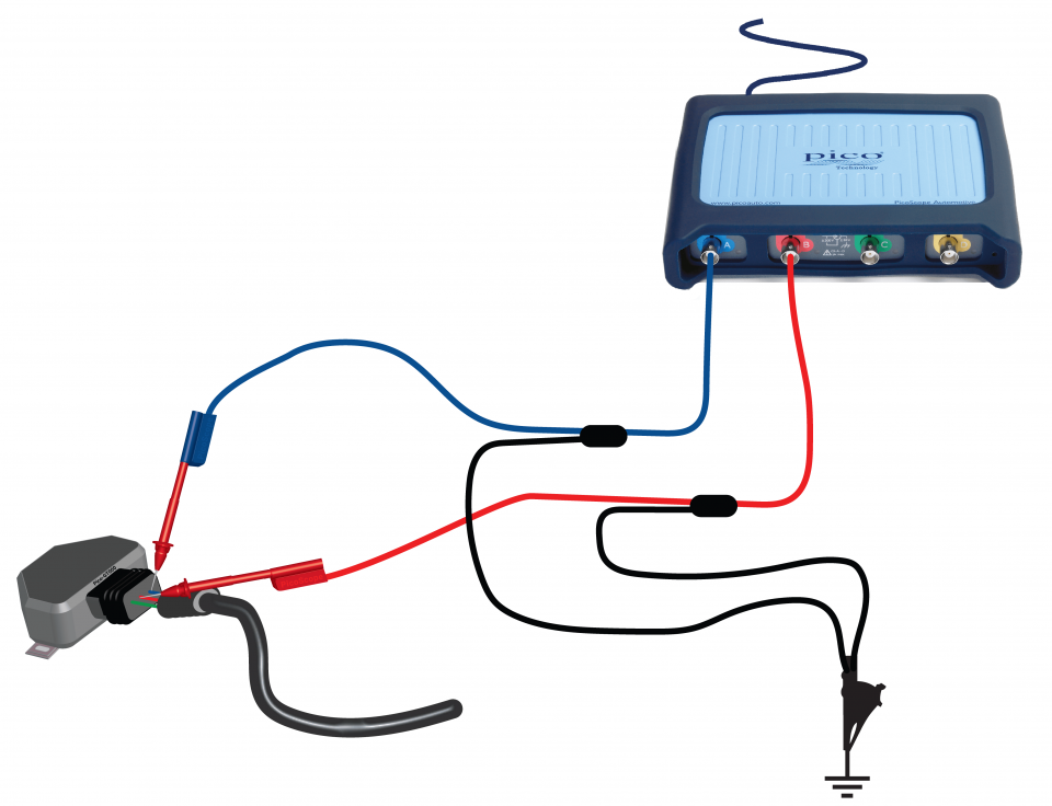
View connection guidance notes.
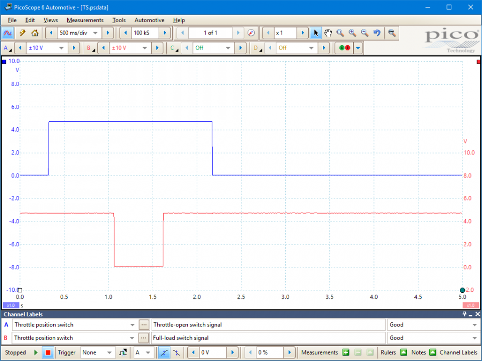
These known good waveforms have the following characteristics:
Channel A indicates the operation of the (normally closed) idle position switch.
Channel B indicates the operation of the (normally open) full-throttle position switch.
There is no drop-out, noise, or hashing in either output signal.
Go to the drop-down menu bar at the lower left corner of the Waveform Library window and select, Throttle position switch.


The throttle position switch signals the movement and position of the throttle valve to the Engine Control Module (ECM). The switch unit is installed at the throttle housing and attached to the throttle butterfly spindle.
Throttle position switches can be configured in different ways, so it will be necessary to check manufacturer specifications for terminal and switching data. However, the general principles of operation are similar.
Inside the unit there are two sets of contacts, with each having an open or a closed state. This allows it to signal three possible throttle position states, such as:
The throttle position switch is usually a three-wire device with a 5 volts supply (12 volts on some very early systems). A typical pin configuration might be (Hella manufactured switch):
Throttle position switch faults can be both electrical and mechanical:
A faulty throttle valve switch can cause:
Selection of component related Diagnostic Trouble Codes (DTCs):
P0068
P0120
P0121
P0122
P0123
P0124
P0220
P0221
P0222
P0223
P0224
P0225
P0226
P0227
P0228
P0229
P0510
View more
GT028
Disclaimer
This help topic is subject to changes without notification. The information within is carefully checked and considered to be correct. This information is an example of our investigations and findings and is not a definitive procedure.
Pico Technology accepts no responsibility for inaccuracies. Each vehicle may be different and require unique test
settings.
We know that our PicoScope users are clever and creative and we’d love to receive your ideas for improvement on this test. Click the Add comment button to leave your feedback.


