PicoScope 7 Automotive
Available for Windows, Mac, and Linux, the next evolution of our diagnostic scope software is now available.
Automotive guided tests
Library of examples on how to perform tests when using PicoScope.

Training
Our collection of training videos, articles, guides and information on training courses.

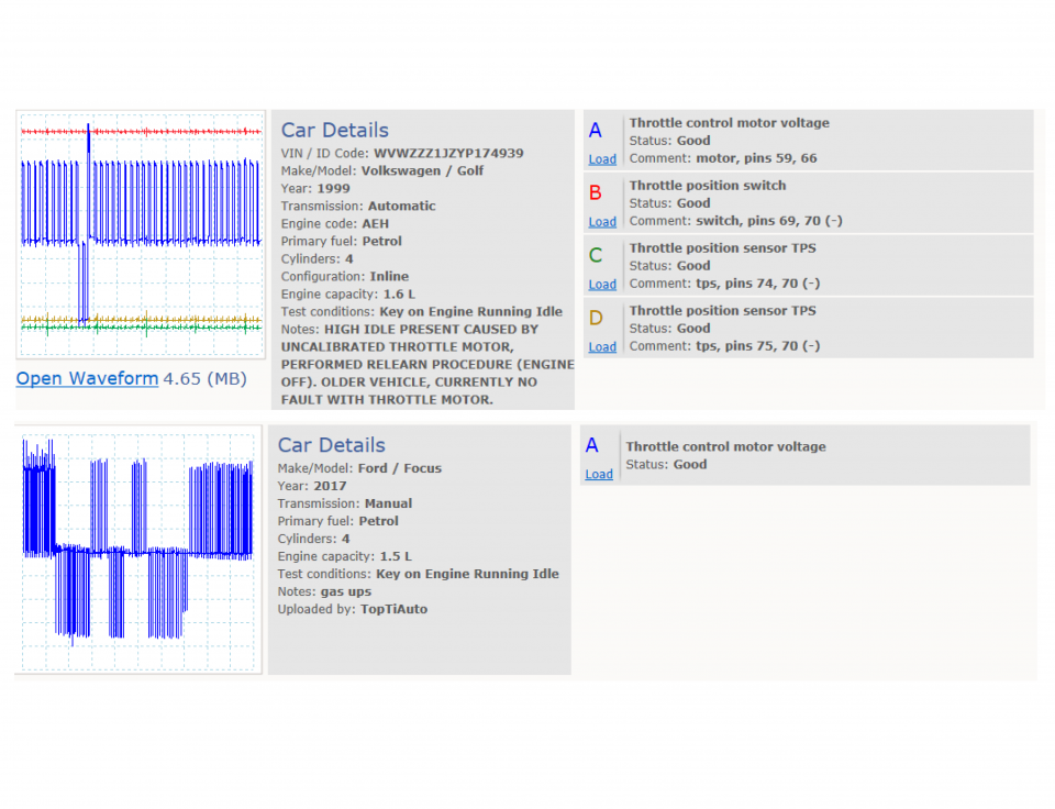
Waveform library
The Waveform Library is a global database of waveforms uploaded by PicoScope users.

Case studies
Real-life case studies show how the professionals use PicoScope to diagnose vehicle faults.

A to Z of PicoScope
Detailed description of various PicoScope software and hardware features.

Videos
Training resources and demonstrations on PicoScope and the Automotive Diagnostics Kit.

Newsletter
Archive of our monthly Automotive Newsletters.

Documentation
Download manuals, brochures, posters, and training materials.

Reviews and awards
Accolades for the preferred diagnostic tool for service centers and vehicle manufacturers.


Multimeter Probes

Back-pinning Probe Set

PicoScope Battery Clip

Flexible Back-pinning Probe

Large Dolphin/Gator Clips
*At Pico we are always looking to improve our products. The tools used in this guided test may have been superseded and the products above are our latest versions used to diagnose the fault documented in this case study.
The purpose of this test is to investigate the action of the throttle positioning motor and position sensor at various engine speeds.
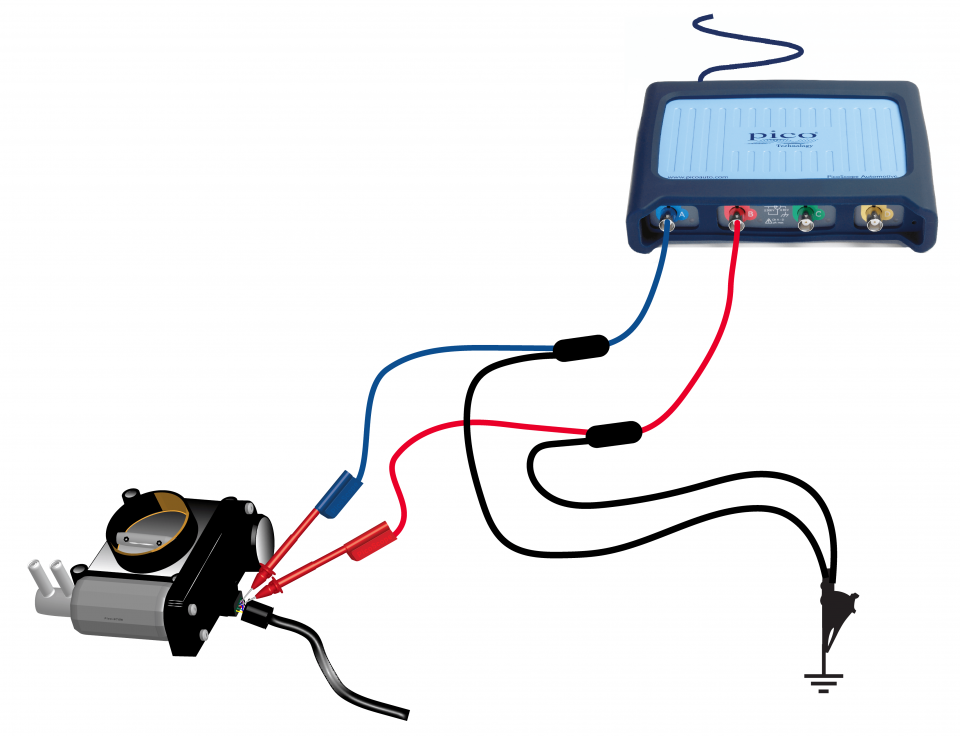
View connection guidance notes.


The dual-trace waveform seen in Figure 2 shows a steady voltage from the Throttle Position Sensor (TPS) illustrated by Channel A (blue trace) at about 0.6 volts. This figure shows the voltage sent from the throttle potentiometer while the engine is at idle and the throttle pedal is at rest. The square wave seen in the red trace switches from 14 volts to 0 volts with a low duty cycle of 15.65%. As the throttle is opened, the voltage from the TPS rises to 1.6 volts and the low duty cycle time switches from 15.65% to 71.34%. This increase in low duty cycle instructs the throttle servo to open to a predetermined angle. The higher TPS voltage and increased low duty cycle can be seen in the second waveform in Figure 3.
The hash on the TPS signal output, in both example waveforms, is due to ignition High Tension (HT) interference and should not be considered a fault.
Go to the drop-down menu bar at the lower left corner of the Waveform Library window and select, Throttle control motor voltage

Throttle servomotors have been fitted to throttle butterflies for several years and are now commonplace on drive-by-wire engine management systems.
The throttle servomotor activates the throttle butterfly in varying increments dependent upon information coming from the vehicle's Electronic Control Module (ECM). The servomotor works in a similar way to a stepper motor but instead of just governing the engines idle speed, the servomotor activates the throttle from idle to the full throttle position.
The system may still use a throttle cable, but this now mainly operates a dual-output throttle position sensor (TPS) that is usually located inside the vehicle's engine compartment with no physical connection to the throttle body. The accelerator pedal sensor is used to communicate the driver's throttle movements to the vehicle's ECM. The component is connected to the throttle pedal by the auxiliary throttle cable (when fitted) which actuates the potentiometer. Systems that do not operate through a throttle cable have a dual-output TPS located on the throttle pedal assembly.
The twin TPS outputs are constantly monitored against each other and any discrepancies are logged as a fault code, causing the Malfunction Indicator Light (MIL) to illuminate. The vehicle's ECM digests all the information from the sensors and determines the angle of throttle opening. This information is sent to the throttle servomotor in the form of a square wave whose duty cycle depends on the angle of throttle butterfly opening. The signal sent to the servomotor has what is called a low duty cycle, which is a measure of the off time or the percentage of time the actuator receives zero volts. (A system that operates in the opposite direction is measured in terms of its high duty cycle, which is the percentage of time that the component receives a supply voltage compared to the off time.)
The example waveform in Figure 2 shows a lower low duty cycle of 15.65% while, in Figure 3, the waveform has been altered to increase its low duty cycle to 71.34%. These figures are for the vehicle being tested and will differ between motor vehicle manufacturers. The relevant technical data should be sought if the vehicle being tested has an engine speed-related problem.
Throttle servomotors are an ideal systems application when used in conjunction with both cruise control to maintain a predefined road speed and traction control systems to limit the power available to the road wheels.
To prevent a faulty sensor from causing an incorrect throttle opening for a given set of inputs, which would cause a safety problem, failsafe settings are installed in the vehicle's ECM.
If the engine fails to rev, the output(s) from the throttle position sensor should be monitored and should rise as the throttle is opened. A constant voltage of 5 volts means that the sensor is either signalling full throttle or has lost its earth connection. Should the low duty cycle fail to increase as the throttle is opened, the ECM is suspect and should be either tested by a recognised specialist or replaced with a new unit.
Our test vehicle was a 2002 Volkswagen Golf with a 10-pin multi-plug. No pin data was available.
GT076
Disclaimer
This help topic is subject to changes without notification. The information within is carefully checked and considered to be correct. This information is an example of our investigations and findings and is not a definitive procedure.
Pico Technology accepts no responsibility for inaccuracies. Each vehicle may be different and require unique test
settings.
We know that our PicoScope users are clever and creative and we’d love to receive your ideas for improvement on this test. Click the Add comment button to leave your feedback.
Ines
November 15 2018
It’s nearly impossible to find well-informed people
on this topic, but you seem like you know what you’re talking about!
Thanks 우리카지노계열


