PicoScope 7 Automotive
Available for Windows, Mac, and Linux, the next evolution of our diagnostic scope software is now available.
Automotive guided tests
Library of examples on how to perform tests when using PicoScope.

Training
Our collection of training videos, articles, guides and information on training courses.

Waveform library
The Waveform Library is a global database of waveforms uploaded by PicoScope users.

Case studies
Real-life case studies show how the professionals use PicoScope to diagnose vehicle faults.

A to Z of PicoScope
Detailed description of various PicoScope software and hardware features.

Videos
Training resources and demonstrations on PicoScope and the Automotive Diagnostics Kit.

Newsletter
Archive of our monthly Automotive Newsletters.

Documentation
Download manuals, brochures, posters, and training materials.

Reviews and awards
Accolades for the preferred diagnostic tool for service centers and vehicle manufacturers.


Back-pinning Probe Set

Large Dolphin/Gator Clips
*At Pico we are always looking to improve our products. The tools used in this guided test may have been superseded and the products above are our latest versions used to diagnose the fault documented in this case study.
The purpose of this test is to investigate throttle stepper motor positioning signals at varying engine idle speeds.

View connection guidance notes.
Note
Dependent on motor type there may be up to four signal circuits.
The engine must be below normal operating temperature to capture the cold idle signal.
The stepper or stepper motor is a small electromechanical device that allows either an air by-pass circuit or a throttle opening to alter in position depending on the amounts that the stepper is indexed.
Invariably it will be used to control the idle speed when an idle speed control valve is not employed. The stepper may control an 'air bypass' circuit by having 4 or 5 connections back to the Electronic Control Module (ECM). The earth's enable the control unit to move the motor in a series of 'steps' and the contacts are earthed to ground via the ECM.
The stepper motor may also be attached to the throttle housing. A small control rod will move onto the throttle lever and adjust the butterfly opening in very precise increments.
The individual earth paths can be checked using the oscilloscope. The waveforms should be similar on each path. Variations may be seen between different systems.
Go to the drop-down menu bar at the lower left corner of the Waveform Library window and select, Idle speed stepper motor voltage.


The stepper or stepper motor is a small electro-mechanical device that allows either an air by-pass circuit or a throttle opening to alter in position depending on the amounts that the stepper is indexed. Invariably it will be used to control the idle speed when an idle speed control valve is not employed.
Two popular types are described below:
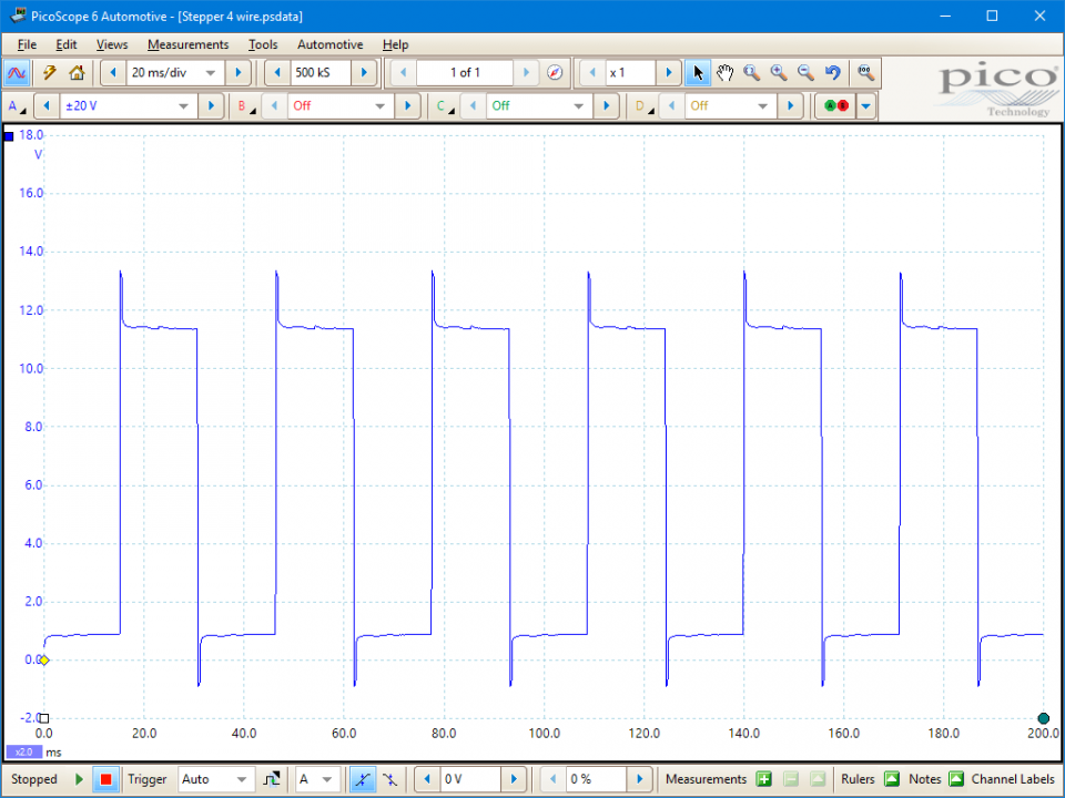
4-wire stepper motor
With the 4-wire stepper motor, the first circuit being a set of contacts is known as the idle tracking switch. The other circuit is controlled by the ECM but only when the idle switch is closed. The second circuit maintains the idle speed when the engine is either hot or cold.
When the engine is cold the idle speed is increased to overcome the cold engine characteristics. When the throttle is released the stepper motor slowly returns the speed back to idle to avoid the engine from stalling.
The four terminals are as follows:
Pin 1 is the idle switch return and will be open circuit at idle.
Pin 2 is the idle switch signal and again, open at idle.
Pin 3 is the stepper motor signal positive at five volts.
Pin 4 is the stepper motor signal negative.
When testing there should be 4 to 6 ohms resistance between pins 3 & 4. Between pins 1 & 2 there should be infinity with the throttle closed, and closed circuit when the throttle is open.
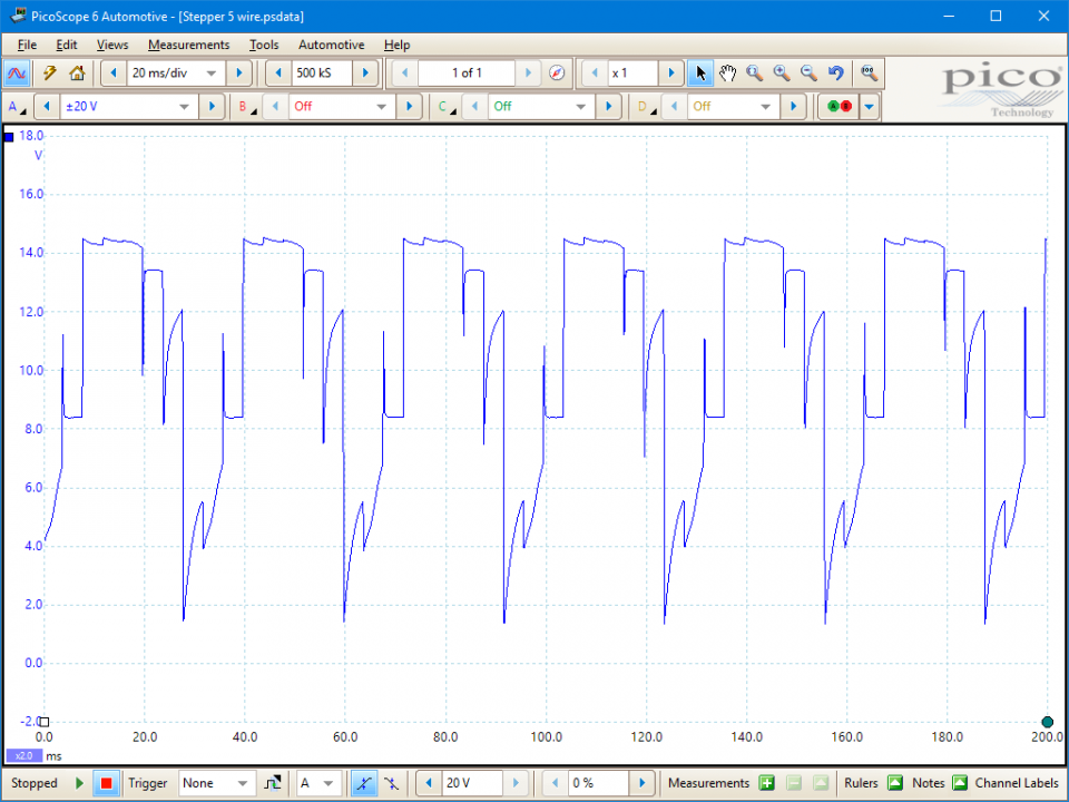
5-wire stepper motor
The stepper may control an 'air bypass' circuit by having a 12 volt supply and a succession of 4 earth paths, as shown in Figure 2. These earths enable the control unit to move the motor in a series of 'steps' and the contacts are earthed to ground via the ECM.
The stepper motor may also be attached to the throttle housing, a small control rod will move onto the throttle lever and adjust the butterfly opening in very precise increments.
When used in either of these two examples, it will maintain the idle speed and avoid the engine from slowing regardless of electrical or mechanical loads. This component is also responsible for the increased idle speed when the engine is cold.
Selection of component related Diagnostic Trouble Codes (DTCs)
P1554 Idle Speed Contr.Throttle Pos. Basic Setting Conditions not met
P1559 Idle Speed Contr.Throttle Pos. Adaptation Malfunction
P1564 Idle Speed Contr.Throttle Pos. Low Voltage During Adaptation
P1565 Idle Speed Control Throttle Position lower limit not attained
P1568 Idle Speed Contr.Throttle Pos. mechanical Malfunction
P1579 Idle Speed Contr.Throttle Pos. Adaptation not started
P1581 Idle Speed Contr.Throttle Pos. Basic Setting Not Carried Out
P1789 Idle Speed Intervention Circ. Error Message from Engine Contr.
GT040-EN
Disclaimer
This help topic is subject to changes without notification. The information within is carefully checked and considered to be correct. This information is an example of our investigations and findings and is not a definitive procedure.
Pico Technology accepts no responsibility for inaccuracies. Each vehicle may be different and require unique test
settings.
We know that our PicoScope users are clever and creative and we’d love to receive your ideas for improvement on this test. Click the Add comment button to leave your feedback.


