PicoScope 7 Automotive
Available for Windows, Mac, and Linux, the next evolution of our diagnostic scope software is now available.
Automotive guided tests
Library of examples on how to perform tests when using PicoScope.

Training
Our collection of training videos, articles, guides and information on training courses.

Waveform library
The Waveform Library is a global database of waveforms uploaded by PicoScope users.

Case studies
Real-life case studies show how the professionals use PicoScope to diagnose vehicle faults.

A to Z of PicoScope
Detailed description of various PicoScope software and hardware features.

Videos
Training resources and demonstrations on PicoScope and the Automotive Diagnostics Kit.

Newsletter
Archive of our monthly Automotive Newsletters.

Documentation
Download manuals, brochures, posters, and training materials.

Reviews and awards
Accolades for the preferred diagnostic tool for service centers and vehicle manufacturers.


20 A / 60 A DC (low amps) current clamp

Multimeter Probes

Back-pinning Probe Set

Flexible Back-pinning Probe

PicoScope Battery Clip
*At Pico we are always looking to improve our products. The tools used in this guided test may have been superseded and the products above are our latest versions used to diagnose the fault documented in this case study.
The purpose of this test is to examine individual glow plug operation through measurement of voltage and current.
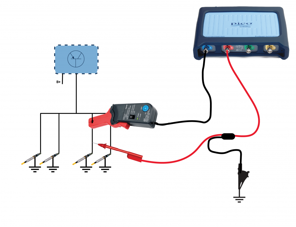
View connection guidance notes.
Note
The glow plugs may not activate if the ambient and engine temperature conditions are not correct.
The orientation of the clamp relative to the wire will determine whether it has a positive or negative output. If a live waveform does not appear on your screen, or appears to be inverted, try reversing the orientation of the clamp.
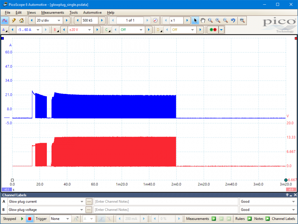
These known good waveforms have the following characteristics:
Channel A
Channel B shows the voltage driving the current in the glow plug circuit:
Go to the drop-down menu bar in the lower left corner of the Waveform Library window and select glow plug current or glow plug voltage.

Glow plugs support diesel fuel combustion and emissions control processes.
Injected diesel fuel ignites if the cylinder charge temperature reaches 850° C during compression. However, this temperature may not be achieved with cold ambient air conditions and engine components. In these circumstances, the glow plugs are activated to heat the cylinder charge and ensure adequate combustion.
Different types of glow plug are available, with rapid glow systems replacing the traditional direct current type. The later systems tend to use ceramic glow plugs, reducing the glow wait time by more than 50%. Their operating temperatures are in the range from 1000° to 1100° C. Manufacturer specifications vary but these systems are not activated with ambient temperatures above 9°C or if the vehicle is driven and engine speed exceeds 2500 rpm.
Rapid glow plugs have two coils internally connected in series, a small heating coil at the plug tip and a larger regulating coil within the plug case. These systems use Pulse Width Modulation (PWM) of the supply voltage to regulate the circuit current and to control glow plug temperature.
Rapid glow systems operate in several modes:
Pre-heat: increases the temperature of the cylinder charge within the combustion chamber prior to start up. As soon as the glow plug temperature has stabilised after their initial activation, they will be switched via PWM to prevent overheating.
Engine cranking: the glow plugs are deactivated to ensure maximum battery capacity is available for the starter motor.
Post heat: the glow plug temperature is regulated via PWM whilst the engine is running. This helps to reduce engine cold running noise and emissions. The post heat run time can vary greatly as it depends on a variety of environmental factors, the engine conditions, and the system design.
Warning: it is often impossible to distinguish standard and rapid glow type glow plugs by visual inspection. Many of the latter systems operate at lower voltages, such as 4 to 5 V or 7 V. Therefore, glow plugs must not be tested using a directly applied voltage, such as that from the battery positive terminal, a test probe or other test device. An unregulated current through the glow plug will cause irreversible damage.
Glow plug circuits are susceptible to a variety of faults, such as:
The most common glow plug fault is a thermal failure from overheating.
Symptoms of failed glow plugs:
Selection of component-related Diagnostic Trouble Codes (DTCs):
P037D
P037E
P037F
P0380
P0381
P0382
P0383
P0384
P064C
P066A
P066B
P066C
P066D
P066E
P066F
P0670
P0671
P0672
P0673
P0674
P0675
P0676
P0677
P0678
P0679
P067A
P067B
P067C
P067D
P067E
P067F
P0680
P0681
P0682
P0683
P0684
P068C
P068D
P068E
P068F
P069A
P069B
P069C
P069D
P06B9
P06BA
P06BB
P06BC
P06BD
P06BE
P06BF
P06C0
P06C1
P06C2
P06C3
P06C5
P06C6
P06C7
P06C8
P06C9
P06CA
P06CB
P06CC
P06CD
P06CE
P06CF
P06D0
U0106
U0307
U0407
View more
GT145
Disclaimer
This help topic is subject to changes without notification. The information within is carefully checked and considered to be correct. This information is an example of our investigations and findings and is not a definitive procedure.
Pico Technology accepts no responsibility for inaccuracies. Each vehicle may be different and require unique test
settings.
We know that our PicoScope users are clever and creative and we’d love to receive your ideas for improvement on this test. Click the Add comment button to leave your feedback.


