PicoScope 7 Automotive
Available for Windows, Mac, and Linux, the next evolution of our diagnostic scope software is now available.
Automotive guided tests
Library of examples on how to perform tests when using PicoScope.

Training
Our collection of training videos, articles, guides and information on training courses.

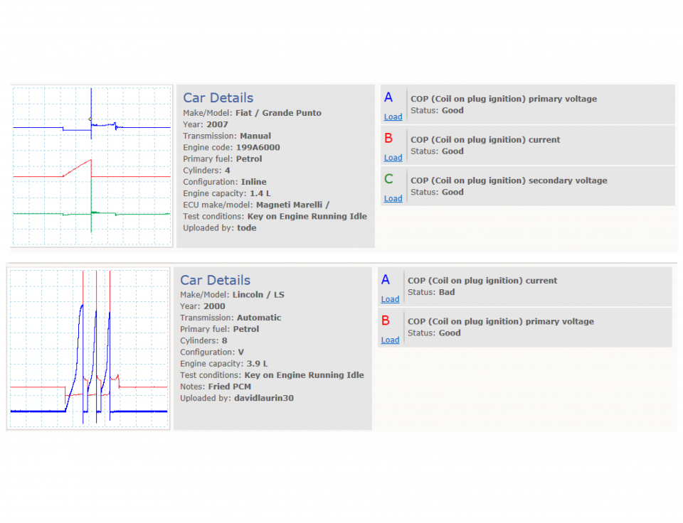
Waveform library
The Waveform Library is a global database of waveforms uploaded by PicoScope users.

Case studies
Real-life case studies show how the professionals use PicoScope to diagnose vehicle faults.

A to Z of PicoScope
Detailed description of various PicoScope software and hardware features.

Videos
Training resources and demonstrations on PicoScope and the Automotive Diagnostics Kit.

Newsletter
Archive of our monthly Automotive Newsletters.

Documentation
Download manuals, brochures, posters, and training materials.

Reviews and awards
Accolades for the preferred diagnostic tool for service centers and vehicle manufacturers.


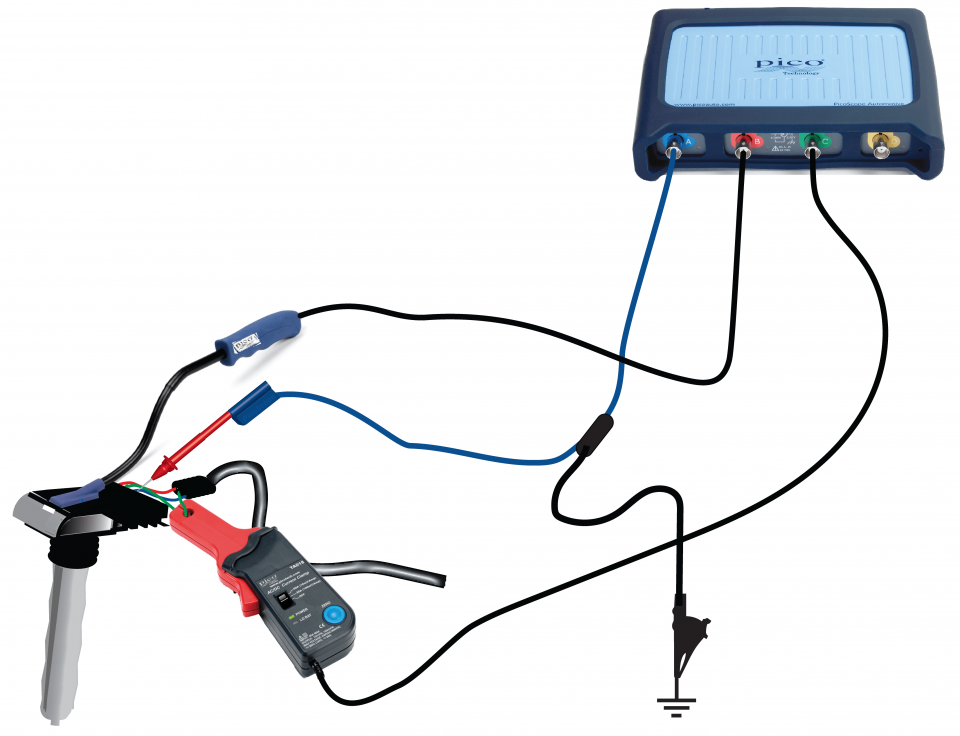
20 A / 60 A DC (low amps) current clamp

Coil On Plug (COP) and Signal Probe

Multimeter Probes
*At Pico we are always looking to improve our products. The tools used in this guided test may have been superseded and the products above are our latest versions used to diagnose the fault documented in this case study.
The purpose of this test is to investigate the operation of the primary and secondary ignition circuits within an externally grounded Coil-On-Plug (COP) type ignition system.
WARNING
This test involves measuring a potentially hazardous voltage.
Please ensure you follow manufacturers' safety instructions and working practices and ensure the rated voltage for all accessories you are using meets or exceeds the expected voltage.
To avoid possible damage to your scope, you may need to use an attenuator for this test.
Scopes with a 200 V range, such as PicoScope 4x25 models, do not need an attenuator for this test.
All other PicoScope Automotive models need an attenuator on the channel input. You can use either a 10:1 or a 20:1 attenuator provided that you adjust the PicoScope software accordingly. Select from the appropriate Channel Options menu:
View connection guidance notes.
Note
The orientation of the current clamp relative to the wire will determine whether it has a positive or negative output. If a live waveform does not appear on your screen, or appears to be inverted, try reversing the orientation of the clamp.
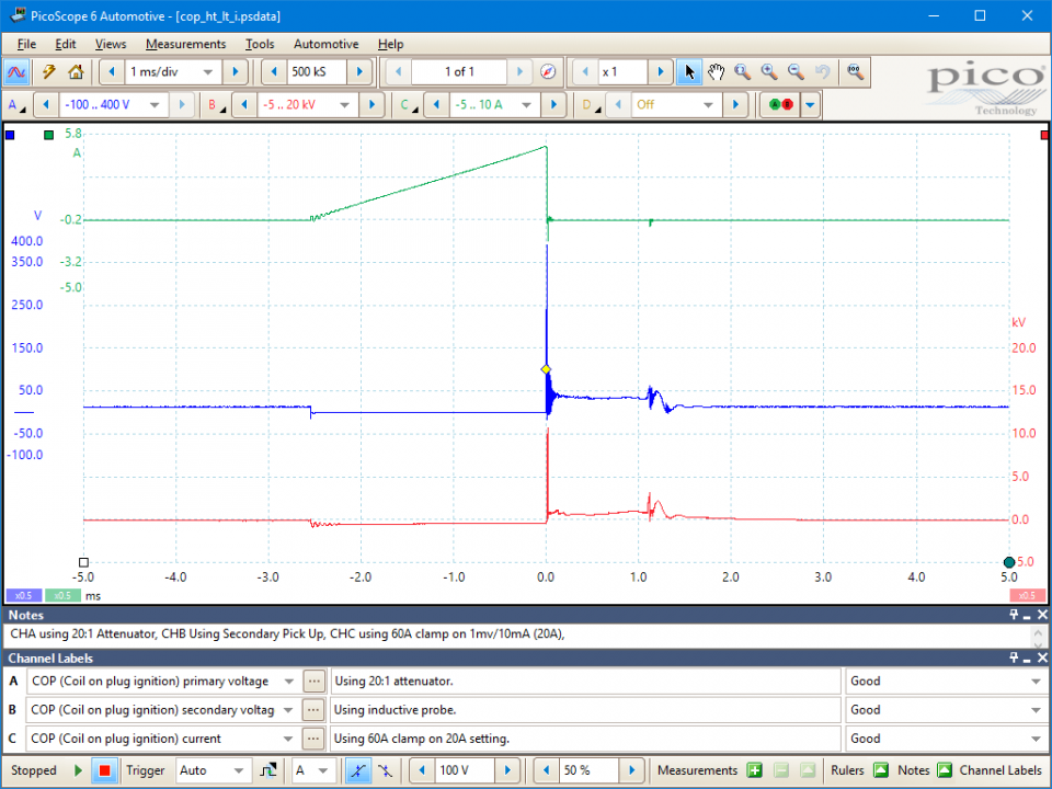
This test produces the three waveforms shown above. Similar waveforms are discussed in the following topics:
Go to the drop-down menu bar at the lower left corner of the Waveform Library window and select, COP (Coil on plug ignition) secondary voltage.
GT079
Disclaimer
This help topic is subject to changes without notification. The information within is carefully checked and considered to be correct. This information is an example of our investigations and findings and is not a definitive procedure.
Pico Technology accepts no responsibility for inaccuracies. Each vehicle may be different and require unique test
settings.
We know that our PicoScope users are clever and creative and we’d love to receive your ideas for improvement on this test. Click the Add comment button to leave your feedback.