PicoScope 7 Automotive
Available for Windows, Mac, and Linux, the next evolution of our diagnostic scope software is now available.
Automotive guided tests
Library of examples on how to perform tests when using PicoScope.

Training
Our collection of training videos, articles, guides and information on training courses.

Waveform library
The Waveform Library is a global database of waveforms uploaded by PicoScope users.

Case studies
Real-life case studies show how the professionals use PicoScope to diagnose vehicle faults.

A to Z of PicoScope
Detailed description of various PicoScope software and hardware features.

Videos
Training resources and demonstrations on PicoScope and the Automotive Diagnostics Kit.

Newsletter
Archive of our monthly Automotive Newsletters.

Documentation
Download manuals, brochures, posters, and training materials.

Reviews and awards
Accolades for the preferred diagnostic tool for service centers and vehicle manufacturers.


Secondary ignition pickup (capacitive with BNC)
*At Pico we are always looking to improve our products. The tool used in this guided test may have been superseded and the product above is our latest version used to diagnose the fault documented in this case study.
Note: This test is suitable for either the negative-fired wasted-spark coil pack or a coil-per-plug system.
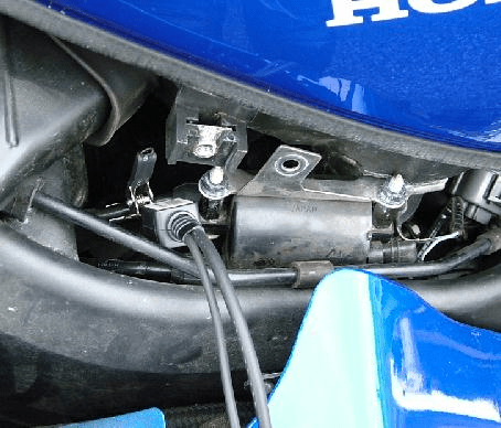
Plug the secondary ignition pick-up lead into Channel A of the scope. Clamp the pick-up around a negative HT lead. It may also be possible to use the HT probe. The HT pick-up connection is illustrated in Figure 1.
In this example the fuel tank securing bolts had to be removed and the tank carefully lifted slightly. The coil pack retaining screw was also removed to gain access to the wasted-spark coil pack HT wires.
With the example waveform displayed on the screen you can now hit the space bar to start looking at live readings.
 waveform")
When the negative-fired plug kVs (kilovolts) are recorded on a 'double-ended coil' system, the voltage seen on the waveform should be in the 'upright position' and not inverted as this would suggest that the inappropriate HT lead has been chosen.
The plug voltage while the engine is running fluctuates continuously and the scope picture moves up and down. To record the maximum voltage seen at the spark plug, the voltage should be taken from the 'Ch A: Maximum (kV)' reading at the bottom of the screen.
Snap the throttle and observe the voltage requirements when the engine is under load. This is the only time that the plugs are placed under any strain and is a fair assessment of how they will perform on the road.
The second part of the waveform can be seen running at approximately 1.5 kV, and is known as the sparkline voltage. This second voltage is the voltage required to keep the plug running after its initial spark to jump the gap. This voltage is proportional to the resistance within the secondary circuit. The length of the line can be seen to run for approximately 1.4 ms. This is the spark duration, the length of time the spark is flowing across the plug gap.
Situated within the coil's primary winding is the secondary winding. This winding is coiled around a multi-laminated iron core and has about 20,000 to 30,000 turns. One end is connected to the primary terminal and the other to the coil tower.
The High Tension (HT) voltage is produced by mutual induction between the primary winding and the secondary winding. The central soft iron core intensifies the magnetic field between them.
The voltage measured at the spark plug is the voltage required to jump the plug gap in varying conditions. This voltage is determined by any of the following:
| The plug kVs will be increased by | The plug kVs will be decreased by |
|---|---|
| large plug gaps | small plug gaps |
| worn spark plugs | low compression |
| a break in a plug lead | rich mixture |
| a lean mixture | incorrect ignition timing |
| tracking to earth | |
| fouled plugs |
The plug kilovolt (kV) requirement of older engines tends to be lower than that of modern engines, as the later designs run higher compression ratios and leaner air / fuel ratios and have larger spark plug gaps.
Modern engines with double-ended coil systems invaribly have the advantages of a constant-energy electronic ignition.
Double-ended coil systems have their own disadvantages (compared with coil-per-cyclinder systems) by having half of the plugs firing with an aceeptable negative voltage, while the other half are fired by the less acceptable positive polarity. This has the effect of greater plug wear on the positive-fired plugs.
This system, becuase of its nature, fires the plugs each revolution, instead of every other, and is known as a wasted-spark system. This does not mean that the plugs wear at twice the normal rate, as the wasted spark is on the exhaust stroke and is therefore under no compression. If the spark plugs are removed after several thousand miles and examined, two of the plugs will have relatively square electrodes, while the plugs that have been fired positive will have proonounced plug wear.
See the plugs kVs increased / decreased table above.
Not applicable.
AT117-3
Disclaimer
This help topic is subject to changes without notification. The information within is carefully checked and considered to be correct. This information is an example of our investigations and findings and is not a definitive procedure.
Pico Technology accepts no responsibility for inaccuracies. Each vehicle may be different and require unique test
settings.
We know that our PicoScope users are clever and creative and we’d love to receive your ideas for improvement on this test. Click the Add comment button to leave your feedback.


