PicoScope 7 Automotive
Available for Windows, Mac, and Linux, the next evolution of our diagnostic scope software is now available.
Automotive guided tests
Library of examples on how to perform tests when using PicoScope.

Training
Our collection of training videos, articles, guides and information on training courses.

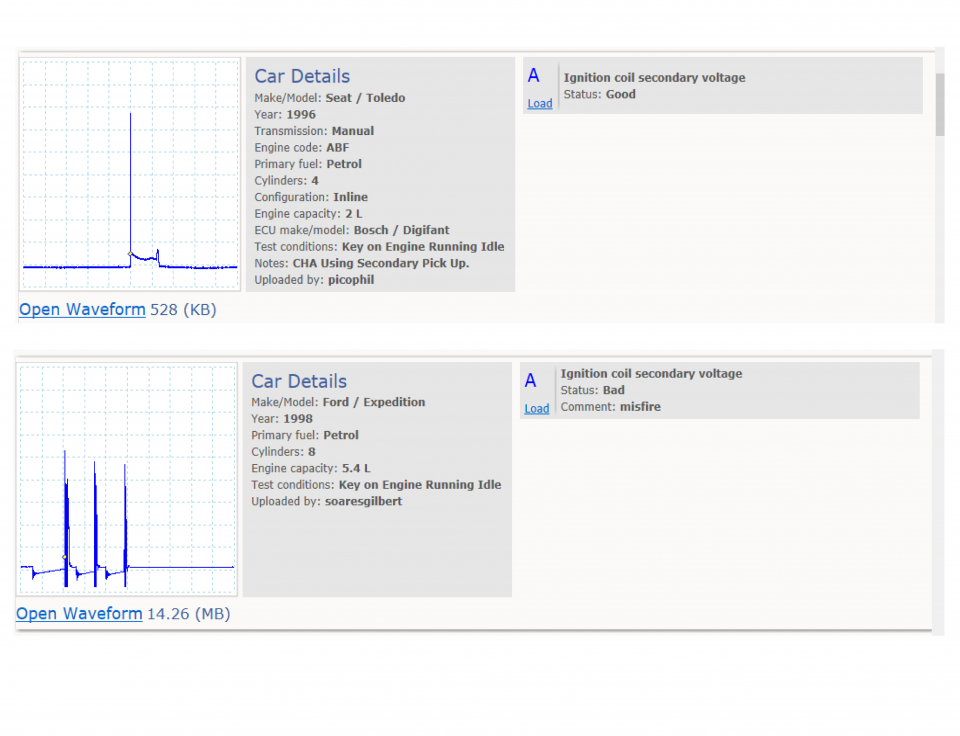
Waveform library
The Waveform Library is a global database of waveforms uploaded by PicoScope users.

Case studies
Real-life case studies show how the professionals use PicoScope to diagnose vehicle faults.

A to Z of PicoScope
Detailed description of various PicoScope software and hardware features.

Videos
Training resources and demonstrations on PicoScope and the Automotive Diagnostics Kit.

Newsletter
Archive of our monthly Automotive Newsletters.

Documentation
Download manuals, brochures, posters, and training materials.

Reviews and awards
Accolades for the preferred diagnostic tool for service centers and vehicle manufacturers.


Secondary ignition pickup (capacitive with BNC)
*At Pico we are always looking to improve our products. The tool used in this guided test may have been superseded and the product above is our latest version used to diagnose the fault documented in this case study.
The purpose of this test is to evaluate the secondary ignition system, mixture, and combustion process, from the secondary voltage picked up on the distributor king lead.
WARNING
Uninsulated HT pickups are designed to clip around double-insulated HT leads only – they are not designed for direct connection to a hazardous live voltage.
To prevent injury or death, when connecting or disconnecting an HT pickup:
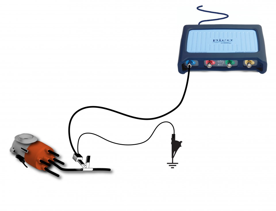
View connection guidance notes.
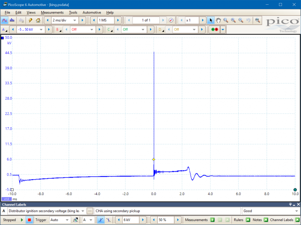
This known good waveform has the following characteristics:
Go to the drop-down menu bar at the lower left corner of the Waveform Library window and select Ignition coil secondary voltage.
General principles
All (inductive) spark ignition systems use one or more ignition coils. The coils act as both an accumulator, to store energy, and a step-up transformer, to generate the high voltages necessary to produce an electrical spark within a combustion chamber.
An ignition coil consists of a primary coil and a secondary coil, wound around each other in close proximity. The secondary coil has a high ratio of windings to the primary coil. This arrangement creates conditions of high mutual inductance, meaning changes in the magnetic field in the primary coil will produce changes in voltage in the secondary coil.
The primary coil is connected within the primary circuit. When current flows in the primary circuit, energy builds within the coil’s magnetic field. If the current is quickly removed, the magnetic field rapidly collapses and induces a high voltage in the secondary coil. The high voltage is delivered to a spark plug via a secondary circuit.
The period during which the current flows within the primary circuit is known as the dwell period (or the dwell angle, if referenced to the angle of crankshaft rotation). The dwell period determines the charging time of the coil and, therefore, partly controls the energy it stores.
The current and dwell period are Key Performance Indicators (KPIs) for primary circuit control. Please refer to manufacturer technical information to find the specifications for your vehicle.
Distributor ignition
Distributor based ignition systems use a single ignition coil.
The switching of the primary circuit can be controlled using one of two mechanisms:
Most mechanically triggered primary circuits require a ballast resistor to regulate the current flow, whereas a transistorised system is able to vary the current more freely.
A component rotating internally within the distributor, the rotor, directs the secondary voltages to each of the engine’s spark plugs, in their firing order, as it passes peripheral electrodes connected to the spark plug leads.
Spark generation
A spark plug provides an insulated path for electrical energy to reach the combustion chamber. It consists of two electrodes (a central electrode and an earth electrode) separated by an insulator. A small air gap, the spark plug gap, exists between the electrodes.
Any voltage difference between the electrodes will create an electric field across the spark plug gap. If the voltage is sufficiently high, the electric field will ionize the air/fuel mixture, turning it from an insulator to a conductor. A current is driven through the mixture by the remaining energy within the ignition system, triggering and sustaining the spark.
Spark diagnostics
The potential difference (voltage) at which mixture ionization occurs is known as the plug kV. The following factors increase plug kV:
The potential difference during which the spark is sustained is known as the sparkline kV.
The electrical energy within the secondary system is finite so the spark is sustained for a limited period, known as the spark duration.
There is an inversely proportional relationship between sparkline kV and spark duration. If the sparkline kV is too high, the spark duration will be too short, and vice versa.
During a spark event, the sparkline kV may:
A misfire may occur if there is too little energy within the ignition system - for example, if the coil is faulty or there are shorts or high resistance in the primary or secondary circuits.
When the mixture ionization can no longer continue, the current and sparkline kV collapse, leaving the remaining energy to oscillate and dissipate through the coil. These are called coil oscillations.
The plug kV, sparkline kV, spark duration and coil oscillations are ignition system KPIs. Please refer to manufacturer technical information to find the specifications for your vehicle.
GT046-EN
Disclaimer
This help topic is subject to changes without notification. The information within is carefully checked and considered to be correct. This information is an example of our investigations and findings and is not a definitive procedure.
Pico Technology accepts no responsibility for inaccuracies. Each vehicle may be different and require unique test
settings.
We know that our PicoScope users are clever and creative and we’d love to receive your ideas for improvement on this test. Click the Add comment button to leave your feedback.


