PicoScope 7 Automotive
Available for Windows, Mac, and Linux, the next evolution of our diagnostic scope software is now available.
Automotive guided tests
Library of examples on how to perform tests when using PicoScope.

Training
Our collection of training videos, articles, guides and information on training courses.

Waveform library
The Waveform Library is a global database of waveforms uploaded by PicoScope users.

Case studies
Real-life case studies show how the professionals use PicoScope to diagnose vehicle faults.

A to Z of PicoScope
Detailed description of various PicoScope software and hardware features.

Videos
Training resources and demonstrations on PicoScope and the Automotive Diagnostics Kit.

Newsletter
Archive of our monthly Automotive Newsletters.

Documentation
Download manuals, brochures, posters, and training materials.

Reviews and awards
Accolades for the preferred diagnostic tool for service centers and vehicle manufacturers.


HT Extension Lead

HT Extension Lead (set of 4 leads)

Secondary ignition pickup (capacitive with BNC)
*At Pico we are always looking to improve our products. The tools used in this guided test may have been superseded and the products above are our latest versions used to diagnose the fault documented in this case study.
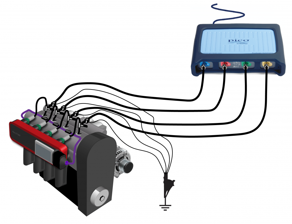
The purpose of this test is to examine all the secondary waveforms from a Multi-Coil-on-Plug four-cylinder ignition unit.
WARNING
Uninsulated HT pickups are designed to clip around double-insulated HT leads only – they are not designed for direct connection to a hazardous live voltage.
To prevent injury or death, when connecting or disconnecting an HT pickup:
Note
Many multi-coil pack systems employ wasted spark coils, this means there will be both negative and positive fired spark plugs.
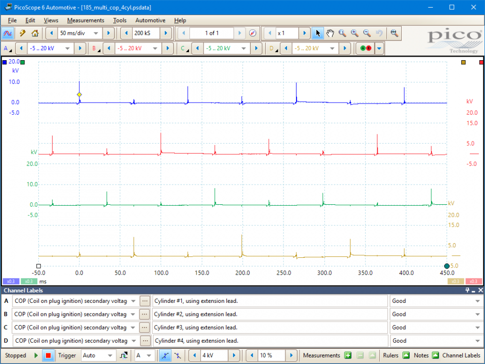
The ignition picture shown in the example waveform is a typical picture from an engine fitted with electronic ignition. The waveform has been taken from the coil-on-plug unit fitted to the Vectra Z22SE engine.
The secondary waveform shows the length of time for which the HT flows across the spark plug's electrode after the initial peak of voltage required to jump the plug gap. This time is referred to as either the 'burn time' or the 'spark duration'. In the illustration, the horizontal voltage line in the centre of the oscilloscope is at fairly constant voltage, but then drops sharply into what is referred to as the 'coil oscillation' period. The 'burn time' is also illustrated in Figure 4.
The coil oscillation period (as illustrated in Figure 5) should display at least 4 peaks (including upper and lower). A loss of peaks indicates that the coil needs substituting. The period between the coil oscillation and the next 'drop down' is when the coil is at rest and there is no voltage in the coil's secondary circuit. The 'drop down' is referred to as the 'negative polarity peak', (as illustrated in Figure 6) and produces a small oscillation in the opposite direction to the plug firing voltage. This is due to the initial switching on of the coil's primary current. The voltage within the coil is only released at the correct point of ignition when the HT spark ignites the air/fuel mixture.
The plug firing voltage is the voltage required to jump the gap at the plug's electrode, commonly known as the 'plug kV'. This is shown in Figure 7. In this example the plug kV is 13.5 kV.

The operation of the coil-on-plug unit is essentially the same as any other ignition system.
Distributorless ignition systems are fitted only to vehicles that have an even number of cylinders such as 2, 4, 6 or 8. This is because two cylinders are connected to one coil that produces a spark in both cylinders at the same time. This is commonly known as a wasted spark system. The two spark plugs are arranged so that one is fired on the power stroke of the engine and the other on the exhaust stroke of the opposing cylinder, offset by 360 degrees. After a complete rotation of the engine, the two cylinders are now on the opposing strokes and the two spark plugs fire again but with opposite roles to before.
On a 4-cylinder engine, there are two coils with individual drivers that usually operate cylinders 1 and 4, and 2 and 3. This means there is a dual spark every 180 degrees, with one of those sparks wasted on an exhaust stroke of the opposing cylinder which is firing on the power stroke.
The only real difference between COP and other ignition systems is that each COP coil is mounted directly onto the spark plug, so the voltage goes directly to the plug electrodes without having to pass through a distributor or plug leads. This direct connection method delivers the strongest spark possible and improves the durability of the ignition system.
GT185
Disclaimer
This help topic is subject to changes without notification. The information within is carefully checked and considered to be correct. This information is an example of our investigations and findings and is not a definitive procedure.
Pico Technology accepts no responsibility for inaccuracies. Each vehicle may be different and require unique test
settings.
We know that our PicoScope users are clever and creative and we’d love to receive your ideas for improvement on this test. Click the Add comment button to leave your feedback.


