PicoScope 7 Automotive
Available for Windows, Mac, and Linux, the next evolution of our diagnostic scope software is now available.
Automotive guided tests
Library of examples on how to perform tests when using PicoScope.

Training
Our collection of training videos, articles, guides and information on training courses.

Waveform library
The Waveform Library is a global database of waveforms uploaded by PicoScope users.

Case studies
Real-life case studies show how the professionals use PicoScope to diagnose vehicle faults.

A to Z of PicoScope
Detailed description of various PicoScope software and hardware features.

Videos
Training resources and demonstrations on PicoScope and the Automotive Diagnostics Kit.

Newsletter
Archive of our monthly Automotive Newsletters.

Documentation
Download manuals, brochures, posters, and training materials.

Reviews and awards
Accolades for the preferred diagnostic tool for service centers and vehicle manufacturers.


Back-pinning Probe Set

PicoScope Battery Clip
*At Pico we are always looking to improve our products. The tools used in this guided test may have been superseded and the products above are our latest versions used to diagnose the fault documented in this case study.
The purpose of this test is to evaluate the idle speed control valve (ISCV) control signal from the Engine Control Module (ECM).
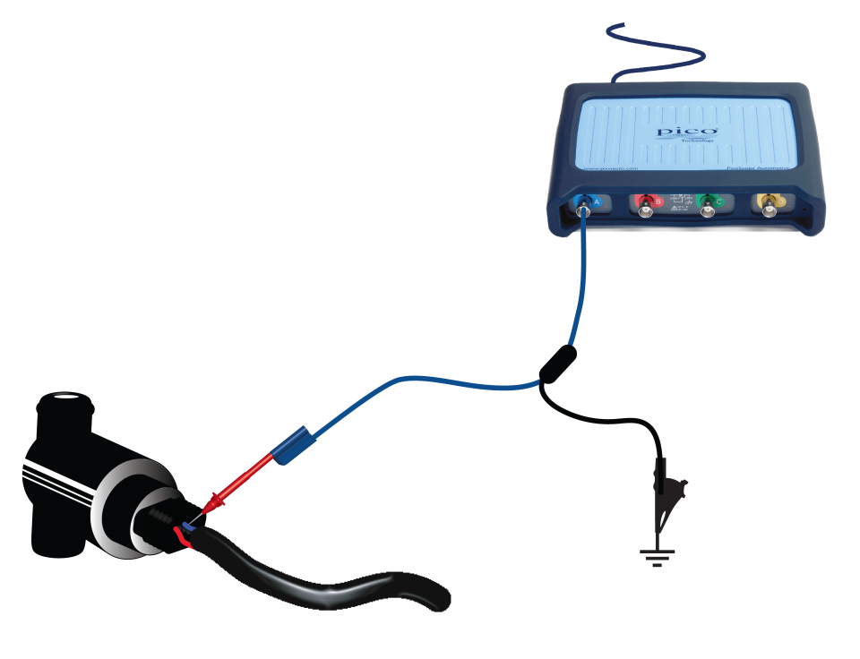
View connection guidance notes.
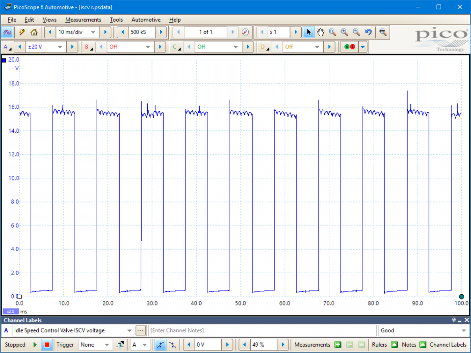
This known good waveform has the following characteristics:
The PWM duty will change with an additional engine load (e.g. from the power steering, air-conditioning or alternator systems etc.).
Go to the drop-down menu bar at the lower left corner of the Waveform Library window and select Idle Speed Control Valve ISCV voltage.


An ISCV is used by the Engine Control Module (ECM) to regulate engine idle speed according to engine temperature and load when there is no driver demand from the accelerator pedal and the throttle is closed.
For example, during cold start conditions, the ECM will seek to quickly raise engine temperature by increasing engine speed to a fast idle, at around 1200 rpm.
With an ISCV, the ECM can maintain and adjust the idle speed for changes in engine load caused by the air conditioning, power steering, automatic transmission, or charging systems, etc.
The rotary ISCV is an electromechanical device that can have either 2 or 3 connections. One connection will be a constant battery voltage from either the ECM or a control relay, and the others providing a single or double switched earth.
The single switched earth system will open the valve in opposition to a closing spring, whereas a double switched earth system will use one circuit to open and the second to close the valve.
The ECM controls the valve opening position by varying the duty cycle of the switched earth signal. Therefore, the greater the on time, the further the valve opens allowing more air into the engine resulting in higher idle speed.
Due to its location, the ISCV is susceptible to carbon fouling. As such the valve may be electrically functioning with a normal waveform but mechanically faulty. In this situation, the valve must be removed for examination, cleaning or replacement.
Symptoms of a faulty idle control valve may be uneven running or cutting out at idle, or fuel trim related diagnostic trouble codes.
Selection of component-related Diagnostic Trouble Codes (DTCs):
P0505 Idle Control System Malfunction
P0506 Idle Control System RPM Lower Than Expected
P0507 Idle Control System RPM Higher Than Expected
P0508 Idle Air Control System Circuit Low
P0509 Idle Air Control System Circuit High
P050A Cold Start Idle Air Control System Performance
P0511 Idle Air Control Circuit
P0518 Idle Air Control Circuit Intermittent
P0519 Idle Air Control System Performance
GT033
Disclaimer
This help topic is subject to changes without notification. The information within is carefully checked and considered to be correct. This information is an example of our investigations and findings and is not a definitive procedure.
Pico Technology accepts no responsibility for inaccuracies. Each vehicle may be different and require unique test
settings.
We know that our PicoScope users are clever and creative and we’d love to receive your ideas for improvement on this test. Click the Add comment button to leave your feedback.


