PicoScope 7 Automotive
Available for Windows, Mac, and Linux, the next evolution of our diagnostic scope software is now available.
Automotive guided tests
Library of examples on how to perform tests when using PicoScope.

Training
Our collection of training videos, articles, guides and information on training courses.

Waveform library
The Waveform Library is a global database of waveforms uploaded by PicoScope users.

Case studies
Real-life case studies show how the professionals use PicoScope to diagnose vehicle faults.

A to Z of PicoScope
Detailed description of various PicoScope software and hardware features.

Videos
Training resources and demonstrations on PicoScope and the Automotive Diagnostics Kit.

Newsletter
Archive of our monthly Automotive Newsletters.

Documentation
Download manuals, brochures, posters, and training materials.

Reviews and awards
Accolades for the preferred diagnostic tool for service centers and vehicle manufacturers.


Back-pinning Probe Set

Flexible Back-pinning Probe

Small Crocodile/Gator Clips

Premium Test Lead: BNC to 4 mm, 3 m

Premium Test Leads: Set of four leads 3 m (TA125 - TA128)
*At Pico we are always looking to improve our products. The tools used in this guided test may have been superseded and the products above are our latest versions used to diagnose the fault documented in this case study.
Plug a BNC test lead into Channel A of the scope. Place a small black clip on the lead end with a black moulding (negative) and a Back-pinning Probe onto the end with a red moulding (positive). Place the small black clip onto the motorcycle frame or battery negative, as illustrated in Figure 1. Check the manufacturer's pin data for the fuel injection Electronic Control Module (ECM) road speed sensor connection Back-pinning probe as in Figure 2. Ensure that a good connection is made through to the wire or terminal and the probe has pierced through the wire and plug insulation.
With the example waveform displayed on the screen you can now hit the space bar to start looking at live readings.
Note: Extreme care should be taken during testing the road speed sensor. Our test was carried out with the bike on the centre stand; first gear was selected, the clutch slowly released and drive to the rear wheel increased to a maximum of 20 mph. If the bike does not have a centre stand then a paddock stand should be used with the correct locating lugs. No live data capture should be attempted whilst riding the motorcycle.

The waveform shown in the illustration above illustrates a typical Hall Effect waveform with the voltage switching from zero to 8 volts. As the road speed increases, the base to peak voltage remains the same but there is an increase in frequency. The switching voltage may differ between motorcycle manufacturers, but the voltage is not as important as the frequency produced.
The Electronic Control Module (ECM) has the ability to adjust the engine's idle speed (where applicable) when the rider is slowing or stationary by using information from the motorcycle's Road Speed Sensor (RSS).
The sensor is a 3-wire device and has a supply at battery voltage, an earth and a digital square wave switching voltage. This switching voltage varies between motorcycle manufacturers.
With the appropriate electrical connection made to the RSS output, raise the rear wheel by using the centre stand. If the motorcycle is not fitted with a centre stand, a 'paddock' stand should be used. Start the engine and select a gear and a waveform switching from zero to a higher voltage should be seen. The voltage seen will alter between motorcycle manufacturers.
As the road speed is increased, the frequency of the switching should be seen to increase. This change can also be measured on a multimeter with a frequency function. The sensor can often be found adjacent to the drive chain's front sprocket. When the motorcycle has a shaft drive, the sensor will still be in a similar position.
With the majority of motorcycle road speed sensors having a digital output, the square wave seen should have clean switching, be uniform in appearance and increase in frequency as the road speed increases. In the illustration above, there are two spurious signals shown. These are nothing more than the engine's High Tension (HT) pulses interfering with the waveform. This should not cause concern.
Our test vehicle was a Honda motorbike. Below is the ECM multiplug pin data. Pin data will be manufacturer and model specific and this data is shown for illustration purposes only.

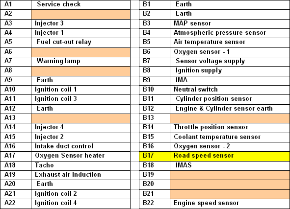
GT108-2
Disclaimer
This help topic is subject to changes without notification. The information within is carefully checked and considered to be correct. This information is an example of our investigations and findings and is not a definitive procedure.
Pico Technology accepts no responsibility for inaccuracies. Each vehicle may be different and require unique test
settings.
We know that our PicoScope users are clever and creative and we’d love to receive your ideas for improvement on this test. Click the Add comment button to leave your feedback.


