PicoScope 7 Automotive
Available for Windows, Mac, and Linux, the next evolution of our diagnostic scope software is now available.
Automotive guided tests
Library of examples on how to perform tests when using PicoScope.

Training
Our collection of training videos, articles, guides and information on training courses.

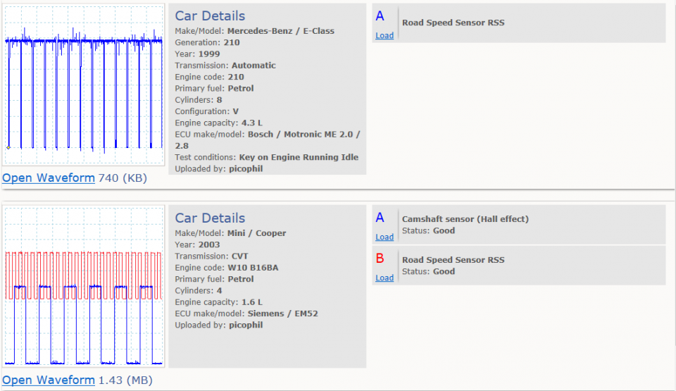
Waveform library
The Waveform Library is a global database of waveforms uploaded by PicoScope users.

Case studies
Real-life case studies show how the professionals use PicoScope to diagnose vehicle faults.

A to Z of PicoScope
Detailed description of various PicoScope software and hardware features.

Videos
Training resources and demonstrations on PicoScope and the Automotive Diagnostics Kit.

Newsletter
Archive of our monthly Automotive Newsletters.

Documentation
Download manuals, brochures, posters, and training materials.

Reviews and awards
Accolades for the preferred diagnostic tool for service centers and vehicle manufacturers.


Back-pinning Probe Set

Flexible Back-pinning Probe

PicoScope Battery Clip
*At Pico we are always looking to improve our products. The tools used in this guided test may have been superseded and the products above are our latest versions used to diagnose the fault documented in this case study.
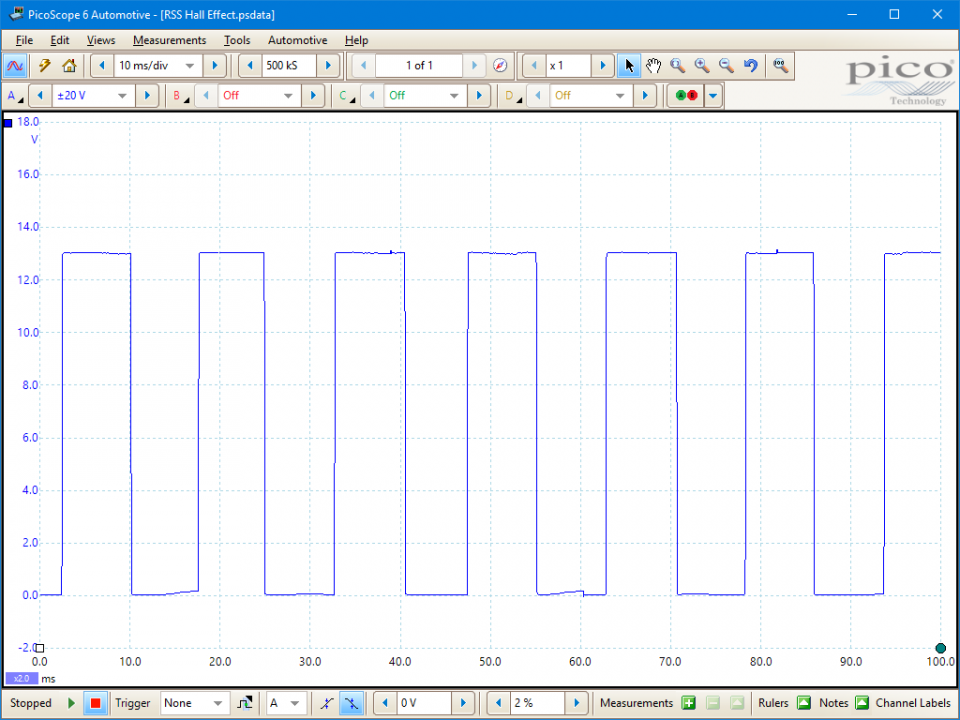
The purpose of this test is to investigate the operation of a Hall Effect Road Speed Sensor based on output voltage and frequency in response to road speed.

View connection guidance notes.
The Control Module has the ability to adjust the engines idle speed when the vehicle is slowing or stationary by using information from the Road Speed Sensor (RSS).
The sensor is a 3 wire device and will have a supply at battery voltage, an earth and a digital square wave output also switching at 12 volts.
With the appropriate electrical connection made to the RSS output, raise one wheel with a trolley and place an axle stand under the suspension unit. Start the engine and select a gear, a waveform switching from 12 volts to zero should be seen. As the road speed is increased the frequency of the switching should be seen to increase. This change can also be measured on a multimeter with frequency capabilities.
The sensor will be located on either the speedometer drive output from the gearbox or to the rear of the speedometer head.
Go to the drop-down menu bar at the lower left corner of the Waveform Library window and select, Road Speed Sensor RSS.

These road speed sensors are now common place on many of today's modern motor vehicles, their function is to provide information to the Engine Control Module (ECM) monitoring the vehicle's momentum.
The control unit now has the ability to determine the idle speed when the vehicle is slowing or stationary and not at any other time during the vehicle's journey. The sensor will be located on either the speedometer drive output from the gearbox or to the rear of the speedometer head.
A typical road speed sensor or Vehicle Speed Sensor (VSS) will produce either an analogue output from a magnetic inductive sensor, or a digital square wave from a voltage driven unit. These sensors can be either a Hall effect device with 3 electrical connections or a Reed switch with 2 connections.
Figure 2 shows a typical road speed sensor which is mounted between the gearbox speedo drive and the speedo drive cable.
The testing of the inductive pick up is identical to a crank angle sensor, resulting in a sine wave and the normal resistance testing. The Hall and Reed switches will provide a square wave and like the inductive sensor, the waveforms can be viewed on an oscilloscope.
GT026
Disclaimer
This help topic is subject to changes without notification. The information within is carefully checked and considered to be correct. This information is an example of our investigations and findings and is not a definitive procedure.
Pico Technology accepts no responsibility for inaccuracies. Each vehicle may be different and require unique test
settings.
We know that our PicoScope users are clever and creative and we’d love to receive your ideas for improvement on this test. Click the Add comment button to leave your feedback.
Phil Rutt
April 01 2022
Thanks for your comment about Road speed sensors and feel this sensor is called many different names by many vehicle manufacturers and at the time of writting this test this was used most commonly used name.
Patrick Lorenz
February 12 2022
When you refer to an RSS in the guided test, do you really mean VSS (vehicle speed sensor)? If you search the internet for RSS or road speed sensor, you don’t get any results. I would like to test my VSS and want to make sure that RSS is the proper guided test.


