PicoScope 7 Automotive
Available for Windows, Mac, and Linux, the next evolution of our diagnostic scope software is now available.
Automotive guided tests
Library of examples on how to perform tests when using PicoScope.

Training
Our collection of training videos, articles, guides and information on training courses.

Waveform library
The Waveform Library is a global database of waveforms uploaded by PicoScope users.

Case studies
Real-life case studies show how the professionals use PicoScope to diagnose vehicle faults.

A to Z of PicoScope
Detailed description of various PicoScope software and hardware features.

Videos
Training resources and demonstrations on PicoScope and the Automotive Diagnostics Kit.

Newsletter
Archive of our monthly Automotive Newsletters.

Documentation
Download manuals, brochures, posters, and training materials.

Reviews and awards
Accolades for the preferred diagnostic tool for service centers and vehicle manufacturers.


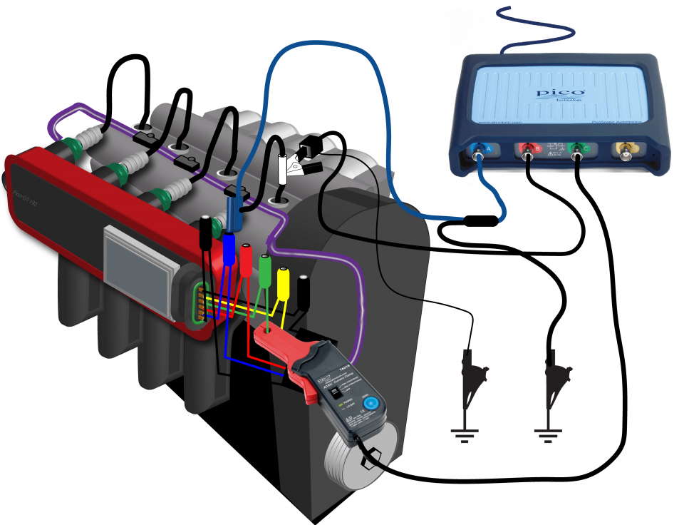
20 A / 60 A DC (low amps) current clamp

Large Dolphin/Gator Clips

Secondary ignition pickup (capacitive with BNC)
*At Pico we are always looking to improve our products. The tools used in this guided test may have been superseded and the products above are our latest versions used to diagnose the fault documented in this case study.
The purpose of this test is to check the primary driver voltage and current against a secondary ignition event for a multi-coil-on-plug unit.
WARNING
Uninsulated HT pickups are designed to clip around double-insulated HT leads only – they are not designed for direct connection to a hazardous live voltage.
To prevent injury or death, when connecting or disconnecting an HT pickup:
View connection guidance notes.
Note
If a secondary waveform cannot be seen then this could be because the output is positive-fired, you have two options.
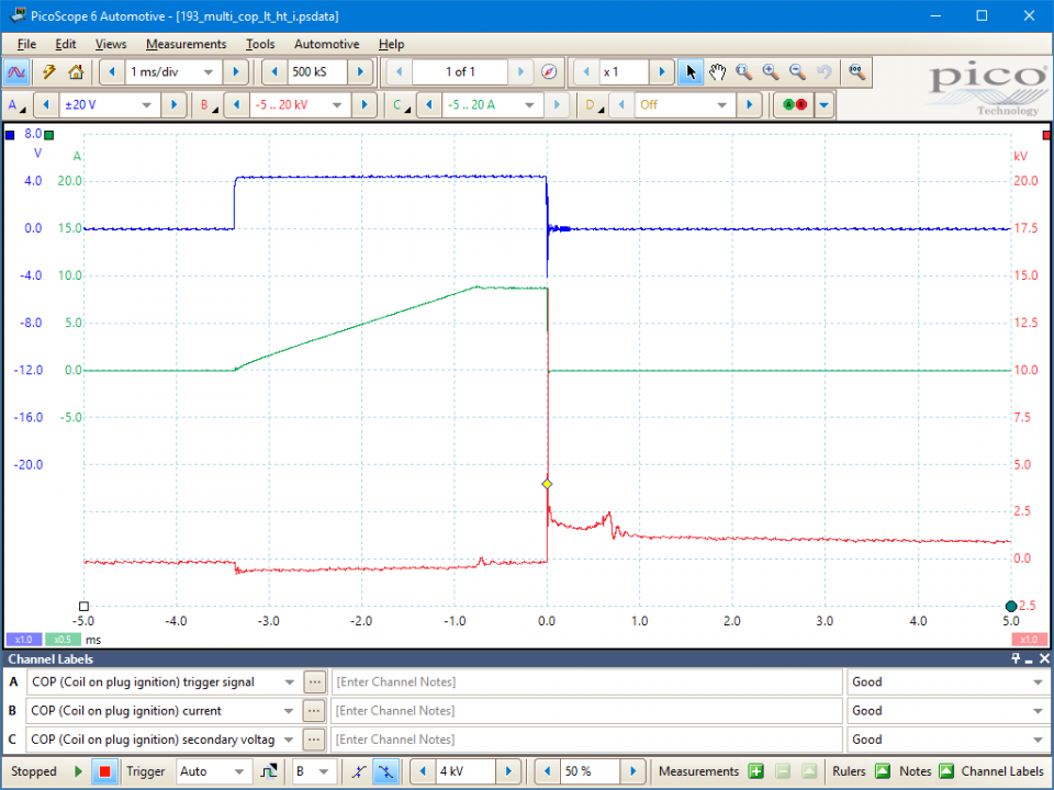
The low-tension (LT) signal switches between zero volts and about 5 volts. When the trigger signal goes high, it causes the coil to switch on. As the voltage returns to zero, the current in the coil's primary winding switches off, the magnetic flux surrounding the winding collapses, this induces a voltage in the secondary and the coil's HT is fired. The switch-on (zero rising to 5 volts) and switch-off (5 volts to zero) points are determined by the vehicle's Electronic Control Module (ECM). This interval between these events is called either the dwell period or the saturation time. The dwell period on an engine with electronic ignition is controlled by the current-limiting circuit in the amplifier or ECM.
The example waveform shows the current-limiting circuit in operation. The current in the primary circuit switches on as the dwell period starts and rises to about 10 amps. It then remains constant for a short time and is released at the point of ignition. The length of time from the initial switching-on point to the moment the current is released depends on engine speed. The lower the engine speed, the shorter the current ramp; then the ramp lengthens with increasing engine revs.
The example waveform shows a typical picture from an engine fitted with electronic ignition. The waveform has been taken from the coil-on-plug unit on the Vectra Z22SE Engine.
The secondary waveform shows the length of time for which the HT flows across the spark plug's electrode after the initial peak of voltage required to jump the plug gap. This time is referred to as either the 'burn time' or the 'spark duration'. In the illustration, the horizontal voltage line in the centre of the oscilloscope is at fairly constant voltage, but then drops sharply into what is referred to as the 'coil oscillation' period.
The coil oscillation period should display at least 4 peaks (including upper and lower). A loss of peaks indicates that the coil needs substituting. The period between the coil oscillation and the next 'drop down' is when the coil is at rest and there is no voltage in the coil's secondary circuit. The 'drop down' is referred to as the 'negative polarity peak' (as illustrated in Figure 7) and produces a small oscillation in the opposite direction to the plug firing voltage. This is due to the initial switching on of the coil's primary current. The voltage within the coil is only released at the correct point of ignition when the HT spark ignites the air/fuel mixture.
The plug firing voltage is the voltage required to jump the gap at the plug's electrode, commonly known as the 'plug kV'. 13.5 kV in this example.

The operation of the Coil-on-Plug Unit is essentially the same as any other ignition system.
Distributorless ignition systems are fitted only to vehicles that have an even number of cylinders such as 2, 4, 6 or 8. This is because two cylinders are connected to one coil that can produce a spark in both cylinders at the same time. This is commonly known as a wasted spark system. The two spark plugs are arranged so that one spark plug is fired on the power stroke of the engine and the other is fired on the exhaust stroke of the opposing cylinder, offset by 360 degrees. After a complete rotation of the engine, the two cylinders are now on the opposing strokes and the two spark plugs fire again but with opposite roles to before.
On a four-cylinder engine, there are 2 coils with individual drivers that tend to operate cylinders 1 and 4, and 2 and 3. This means there is a dual spark every 180 degrees, with one of those sparks wasted on an exhaust stroke of the opposing cylinder which is firing on the power stroke.
The only real difference between COP and other ignition systems is that each COP coil is mounted directly onto the spark plug, so the voltage goes directly to the plug electrodes without having to pass through a distributor or plug leads. This direct connection method delivers the strongest spark possible and improves the durability of the ignition system.
The switch-on (zero rising to 5 volts) and switch-off (5 volts to zero) points of the coil are determined by the vehicle's Electronic Control Module (ECM). The time between these points is called either the dwell period or the coil saturation time. The dwell period on an engine with electronic ignition is controlled by the current-limiting circuit in the amplifier or ECM.
Historically, the supply voltage was present as soon as the ignition switch was turned to the 'on' position. Modern systems, however, do not provide a supply until the key is turned to the 'crank' position and the engine turns. A simple fault such as a non-functioning crank angle sensor may result in a loss of supply voltage, simply because the electronic control circuits do not recognize that the engine is rotating.
The earth connection is essential to the operation of any electrical circuit in an engine. As the current increases in any electrical circuit, so does the voltage drop. An earth return circuit can only be tested while the circuit is under load, so simple continuity testing to earth with a multimeter is inaccurate. As the coil's primary circuit is only complete during the dwell period, the voltage drop should be monitored during this period. The voltage ramp on the earth signal should not exceed 0.5 volts. The flatter the waveform the better: a waveform with virtually no rise shows that the amplifier or module has a perfect earth. If the ramp is too high, the earth connections need to be investigated to identify the offending connection.
The example waveform shows the current limiting circuit in operation. The current in the primary circuit switches on as the dwell period starts, rises to about 10 amps, and remains constant until it is released at the moment of ignition.
As engine speed increases, the dwell angle expands to maintain a constant coil saturation time and therefore constant energy. The coil saturation time can be measured by placing one time ruler at the beginning of the dwell period and the other at the end of the current ramp. The distance between the rulers will remain exactly the same regardless of engine speed.
GT193
Disclaimer
This help topic is subject to changes without notification. The information within is carefully checked and considered to be correct. This information is an example of our investigations and findings and is not a definitive procedure.
Pico Technology accepts no responsibility for inaccuracies. Each vehicle may be different and require unique test
settings.
We know that our PicoScope users are clever and creative and we’d love to receive your ideas for improvement on this test. Click the Add comment button to leave your feedback.


